In November 2025 the EPC, with support from Quanser, launched a new Complex Systems Toolkit, aimed at providing accessible, practical resources for embedding complex systems concepts into engineering education.
The Toolkit launched with an abundance of resources, allowing educators and industry professionals to dive into the ‘what’ and ‘how’ of complex systems with knowledge and guidance articles, discover ready-to-use teaching resources including case studies and other classroom activities, and hear directly from the creators and partners who helped shape the Toolkit with a well-attended launch webinar (now available to watch on demand).
These resources have been well used in their first six months, but we’re not stopping there. We want to add further resources, on topics that are emerging as being of vital importance to students as they graduate and seek work. The first of the topics that we want to cover is intelligent robotics.
What and why?
Intelligent robotics, and the more recent applications to physical AI, generally refers to artificial intelligence systems that are embedded in and interact directly with the physical world, rather than operating purely in digital environments. This includes technologies like robots, autonomous vehicles, and drones that can perceive their surroundings through sensors, process that information using AI models, and take real-world actions. Unlike traditional software-based AI, intelligent robotics applications deal with real-time constraints, uncertainty, and complex environments, requiring tight integration between hardware (like sensors and actuators) and decision-making algorithms.
For engineering students, learning about intelligent robotics and physical AI workflows matters because it sits at the intersection of software, hardware, and real-world problem solving. It forces students to grapple with uncertainty, noisy sensor data, timing constraints, and safety considerations, which are unavoidable in real systems like robots or autonomous vehicles. That experience builds practical intuition about how algorithms behave outside ideal conditions. Engineers who understand this are better equipped to design systems that are robust, adaptive, and resilient. Industries are moving rapidly toward automation, robotics, and intelligent infrastructure, so familiarity with intelligent robotics and physical AI workflows opens doors in fields like manufacturing, healthcare technology, and transportation. It helps engineers think holistically: not just “does the code work?” but “does the system behave safely and effectively in the real world?”.
Contributors sought to develop resources on Intelligent Robotics for inclusion in the toolkit
We are seeking experts in intelligent robotics, from academia, industry, and engineering organisations, to develop resources on this topic for publication in the Complex Systems Toolkit. These resources will inform, guide and aid educators to embed teaching on intelligent robotics into their engineering lessons, modules or courses.
We invite contributors to develop resources in three areas:
Knowledge articles: These are resources that users can access to improve their knowledge or find more information. These are intended to provide theoretical and practical background on intelligent robotics concepts and tools such as modelling or decision-making approaches. While guidance articles focus on “how”, knowledge articles focus on “what”.
Guidance articles: These are resources that users can access to learn how to do something. These are intended to provide practical advice on subjects such as how to explain intelligent robotics to students, or how to assess for skills and competencies in this area. While knowledge articles focus on “what”, guidance articles should focus on “how”.
Teaching activities: These are resources that users can access to help them know what to integrate and implement. These include use cases/case studies which provide examples of intelligent robotics which can be directly utilised in teaching with the suggested tools, as well as other classroom activities such as coursework, project briefs, lesson plans, demonstration simulations, or other exercises.
We’re also looking for experts in intelligent robotics and physical AI to join us as reviewers and working group members.
We are seeking content on the following topics
Resources should reference the topic’s relationship to complex systems and engineering education/graduate skills. We are particularly interested in resources that help engineering educators teach these topics effectively.
Robotics and autonomous systems
Human-robot interaction
Swarm systems and distributed intelligence
Edge AI and embedded intelligence
Cyber-physical systems
Simulation and digital twins
Safety, resilience, and uncertainty
Systems thinking for Intelligent Robotics or Physical AI
Teaching approaches and assessment methods
Read more about the specific content we are looking for (click on the arrows to expand the sections)
Submit a knowledge article
Submit a knowledge article
As well as choosing a topic, you will need to choose an angle for your resource.
For knowledge articles. contributors might consider one of the following:
What it is: explaining the topic and its relation to complex systems.
Why educators should teach it / students should learn it.
Why it should be integrated into engineering education.
An angle of your own choosing.
These articles should connect the why (why must teaching about the topic be present in engineering education?) to the how (how can this be done efficiently and effectively?). Through these tools, we aim to help upskill UK engineering educators so that they feel capable of and confident in integrating complex systems concepts and intelligent robotics topics into their engineering teaching.
Step 1: Read the guidance for submitting a knowledge article
Research:
Knowledge articles are resources that users can access to improve their knowledge or find more information. These are intended to provide theoretical and practical background on complex systems concepts and tools such as modelling or decision-making approaches. While guidance articles focus on “how”, knowledge articles focus on “what”.
Knowledge articles are meant to be overviews that a reader with no prior knowledge of the topic could refer to in order to develop a baseline understanding and learn where to look for additional information (they can reference other sources). They should be understandable to students as well: imagine that an educator might excerpt content from the article to provide their students context on a project or learning activity.
They should be approximately 500-1000 words (although they can be more in depth if necessary) and reference relevant online open-source resources.
Overview:
The articles are meant to be able to stand on their own as a piece of knowledge on a topic; they are also meant to work alongside other articles so that taken together they form a sort of complex systems in engineering handbook.
Purpose:
Each article should inform, explain, and provide knowledge on the topic. Put yourself in the perspective of an engineering educator who is new to the topic.
Content:
The content of the article should be organised and well developed. That is, it should be presented in a logical way and thoroughly explained.
References and resources:
Where additional explanation could be given, it might point to other resources, and where information is presented from another source, it needs to be properly referenced using Harvard referencing.
Format:
Knowledge articles should follow this format:
Premise;
Body of article, divided up into headed sections as necessary;
Knowledge articles should be submitted in Word file format (.doc or .docx).
Also submit any additional resources such as spreadsheets, handouts etc., and ensure that they are in an editable format. Please clarify where in the resource these should be embedded or linked.
Any corresponding images should be submitted in either .jpeg, .jpg or .png format. We need these to be uploaded separately from the Word file, as we will be embedding them in a web page. Please ensure that they are of high resolution and adequate size (we suggest a minimum of 800 pixels wide); that you have the right or permission to use them (bearing in mind they will be published under a Creative Commons license); and that you have added any permissions, sources, credits or other details for them in the body of the document that you are submitting.
To ensure that everyone can use and adapt the Toolkit resources in a way that best fits their teaching or purpose, this work will be licensed under a Creative Commons Attribution-ShareAlike 4.0 International License. Under this licence users are free to share and adapt this material, under terms that they must give appropriate credit and attribution to the original material and indicate if any changes are made.
These articles should also connect the why (why must teaching about this topic be present in engineering education?) to the how (how can this be done efficiently and effectively?). Through these tools, we aim to help upskill UK engineering educators so that they feel capable of and confident in integrating complex systems concepts and intelligent robotics topics into their engineering teaching.
Step 1: Read the guidance for submitting a guidance article
Research:
Guidance articles are resources that users can access to learn how to do something. These are intended to provide practical advice on subjects such as how to explain complex systems to students, or how to assess for skills and competencies in complex systems. While knowledge articles focus on “what”, guidance articles should focus on “how.”
Guidance articles aim to help situate our teaching resources in an educational context and to signpost to additional research and resources on complex systems theory and tools.
They should be approximately 500-1000 words (although they can be more in depth if necessary) and reference relevant online open-source resources.
Overview:
Guidance articles are meant to be able to stand on their own as a piece of guidance on a topic; they are also meant to work alongside other articles so that taken together they form a sort of complex systems in engineering handbook.
Purpose:
Each article should inform, explain, and provide guidance on the topic. Put yourself in the perspective of an engineering educator who is new to the topic.
Content:
The content of the article should be organised and well developed. That is, it should be presented in a logical way and thoroughly explained.
References and resources:
Where additional explanation could be given, it might point to other resources, and where information is presented from another source, it needs to be properly referenced using Harvard referencing.
Format:
Guidance articles should follow this format:
Premise;
Body of article, divided up into headed sections as necessary;
Guidance articles should be submitted in Word file format (.doc or .docx).
Also submit any additional resources such as spreadsheets, handouts etc., and ensure that they are in an editable format. Please clarify where in the resource these should be embedded or linked.
Any corresponding images should be submitted in either .jpeg, .jpg or .png format. We need these to be uploaded separately from the Word file, as we will be embedding them in a web page. Please ensure that they are of high resolution and adequate size (we suggest a minimum of 800 pixels wide); that you have the right or permission to use them (bearing in mind they will be published under a Creative Commons license); and that you have added any permissions, sources, credits or other details for them in the body of the document that you are submitting.
To ensure that everyone can use and adapt the Toolkit resources in a way that best fits their teaching or purpose, this work will be licensed under a Creative Commons Attribution-ShareAlike 4.0 International License. Under this licence users are free to share and adapt this material, under terms that they must give appropriate credit and attribution to the original material and indicate if any changes are made.
As well as choosing a topic, you will need to choose an angle for your resource.
For activities, contributors might consider one of the following:
Case studies that, through a real-world situation, illustrate the topic and its relation to complex systems, use cases for the tools that can be used to model / simulate this, techniques that promote development and use of systems architecture, and effects such as trade-offs, emergent properties, impacts, or unintended consequences. Case studies could also reference the implications for risk, security, ethics, sustainability, teamwork, and communication.
Demonstrator simulations that provide examples of how systems can be modelled.
This could include:
Examples of how the topic relates complex systems
Interactive examples showing how well-intentioned action can lead to failure
Interactive examples showing the best approaches to handling complexity
Teaching/learning activities, coursework, project briefs, lesson plans, modelling or simulation exercise/activities, technical content related to complex systems, worksheets, slides, robotics labs, swarm behaviour activities, system mapping exercises, hardware-in-the-loop demonstrations, digital twin exercises, or other teaching materials.
An angle of your own choosing.
These resources should promote active learning pedagogies and real-world teaching methods by showing how complex systems teaching can be embedded within technical problems and engineering practice. Through these resources, we aim to help upskill UK engineering educators so that they feel capable of and confident in integrating complex systems into their engineering teaching.
Step 1: Read the guidance for submitting a teaching activity/resource
Research:
Teaching activities are resources that users can access to help them know what to integrate and implement. These include use cases/case studies which provide examples of complex systems topics which can be directly utilised in teaching with the suggested tools, as well as other classroom activities such as coursework, project briefs, lesson plans, simulation exercises, robotics labs, swarm behaviour activities, system mapping exercises, hardware-in-the-loop demonstrations, digital twin exercises, or other exercises.
Before you begin, you should review existing Complex Systems Toolkit teaching resources, since we hope that contributions will be fairly consistent in length, style, tone, format and approach. Remember that the audience for these resources is educators seeking to embed complex systems topics within their engineering teaching.
Step 1a: Guidance for submitting a case study
Case studies present real-world scenarios that can be used in teaching about complex systems topics in engineering. They provide students with opportunities to explore complex systems tools, and trade-offs, in authentic contexts, and reflect on decisions made about them.
They are usually based on a real example, although fictionalised cases are acceptable when they are grounded in realistic detail. Case studies should enable students to identify or interpret key features of complex systems topics (feedback loops, interdependence or emergent behaviour) and apply relevant tools or frameworks to make sense of the situation.
Case studies will vary in length depending on scope and resource, but many are around 1500-2000 words. They should reference relevant online open-source resources.
The case study should be presented as a narrative about a complex systems issue in engineering.
Narrative strength: the case should be clearly structured with a compelling and coherent story.
System complexity: it should explore interdependencies, multiple stakeholders and/or competing goals.
Tool integration: systems tools should be mentioned or incorporated (e.g. soft systems methodology, SysML, Agent-based modelling etc).
Activities and Resources: there should be questions, prompts or teaching activities to guide discussion or classroom use.
Authenticity:
Case studies are most effective when they feel like they are realistic, with characters that you can identify or empathise with, and with situations that do not feel fake or staged. Giving characters names and backgrounds, including emotional responses, and referencing real-life experiences help to increase authenticity.
Complexity of issue:
Many cases are either overly complicated so that they become overwhelming, or so straightforward that they can be “solved” quickly. A good strategy is to try to develop multiple dimensions of a case, but not too many that it becomes unwieldy. Additionally, complexity can be added through different parts of the case so that instructors can choose a simpler or more complicated version depending on what they need in their educational context.
Activities and resources:
You should provide a variety of suggestions for discussion points and activities to engage learners, as well as a list of reliable, authoritative open-source online resources, to both help educators prepare and to enhance students’ learning. Where information is presented from another source, it needs to be properly referenced using Harvard referencing.
Educational level and assessment:
Educational level: When writing your case study, you should consider which level it is aimed at. A Beginner level case is aimed at learners who have not had much experience in engaging with this complex systems topic or problem, and usually focuses on only one or two dimensions of a challenge. An Advanced-level case is aimed at learners who have had previous practice in engaging with this complex systems topic or problem, and often addresses multiple challenges. An Intermediate case is somewhere in between.
Assessment: If possible, suggest assessment opportunities for activities within the case, such as marking rubrics or example answers.
Format:
The case study should follow the following format:
Teaching notes (with learning objectives, time needed, materials): This is an overview of the case and its dilemma, and how it relates to AHEP4 and INCOSE competencies.
Learning and teaching resources: A list of reliable, authoritative, open-source online resources that relate to the case and its dilemma. These can be from a variety of sources, such as academic institutions, journals, news websites, business, and so on. We suggest a minimum of five sources that help to provide context to the case and its dilemmas.
Summary of system or context.
Narrative of the case (presenting the complexity).
Questions and activities. This is where you provide suggestions for discussions and activities related to the case and the dilemma.
Further discussion or challenge (optional). Some case studies are sufficiently complex at one dilemma, but if the case requires it you can provide further parts (up to a maximum of three).
Step 1b: Read the guidance for submitting a different teaching activity
Purpose & outcomes:
Teaching activities/tools are intended to support educators’ ability to apply and embed complex systems concepts and topics within their engineering teaching.
Educators need to quickly and easily find help with:
Adapting and integrating existing complex systems resources to their disciplinary context.
Implementing new and different pedagogies that support complex systems learning.
Structuring lessons, modules, and programmes so that complex systems skills and outcomes are central themes.
Thus, these teaching activities/tools will provide crucial guidance for those who may be teaching complex systems related material for the first time, or who are looking for new and different ways to integrate complex systems concepts or topics into their teaching.
Teaching activities/tools may take the form of learning activities, coursework, project briefs, lesson plans, modelling or simulation exercise/activities, technical content related to complex systems, worksheets, slides, robotics labs, swarm behaviour activities, system mapping exercises, hardware-in-the-loop demonstrations, digital twin exercises, or other similar teaching materials.
Imagine that you are an engineering educator who is new to teaching complex systems concepts or topics. You turn to this teaching tool to help you apply and embed these in your module.
Does this resource help introduce or develop concepts related to complex systems or systems thinking so that learners can engage with these topics in the context of engineering?
If not, what is needed to make this possible?
Presentation and clarity:
Depending on the resource, you may choose to provide worksheets, slides, problem sets, narrative prompts, etc.
Is the resource explained in such a way that someone new to teaching complex systems could understand how to use it?
Is the material clearly introduced and described?
Resources and guidance:
Depending on the topic, educators may need additional resources or guidance to support their use of the material. For instance, background information may be required or a technical topic explained.
Have you provided sufficient material so that educators can easily employ the resource?
The teaching activity/tool should follow this format:
Overview:
Short description of what the resource is and what it aims to do.
States how it is related to complex systems or systems thinking topic(s), referring to external content such as INCOSE Competencies and AHEP 4.
Provides an overview of the activity, suggesting how it might be implemented and in what contexts, how long it might take, and any other relevant delivery information.
Details any specific materials or software required for the activity, as well as any modelling or simulation tools to be used.
Lists any learning and teaching resources recommended in order to undertake the activity, including suggested pre-reading or other references.
Explains the activity in as much detail as is required (this will vary depending on the type of material the resource addresses.)
If relevant, provides assessment guidance–marking rubrics, sample answers, etc.
Step 2b: Before you submit, review this checklist:
Does this resource help introduce or develop concepts/topics related to complex systems or systems thinking so that learners can engage with these topics in the context of engineering?
Is the resource explained in such a way that someone new to teaching complex systems could understand how to use it?
Is the material clearly introduced and described?
Have you provided sufficient material so that educators can easily employ the resource?
Step 3: Submitting your teaching activity/resource
Teaching resources should be submitted in Word file format (.doc or .docx).
Also submit any additional resources such as spreadsheets, handouts etc., and ensure that they are in an editable format. Please clarify where in the resource these should be embedded or linked.
Any corresponding images should be submitted in either .jpeg, .jpg or .png format. We need these to be uploaded separately from the Word file, as we will be embedding them in a web page. Please ensure that they are of high resolution and adequate size (we suggest a minimum of 800 pixels wide); that you have the right or permission to use them (bearing in mind they will be published under a Creative Commons license); and that you have added any permissions, sources, credits or other details for them in the body of the document that you are submitting.
To ensure that everyone can use and adapt the Toolkit resources in a way that best fits their teaching or purpose, this work will be licensed under a Creative Commons Attribution-ShareAlike 4.0 International License. Under this licence users are free to share and adapt this material, under terms that they must give appropriate credit and attribution to the original material and indicate if any changes are made.
We are also seeking experts on intelligent robotics/physical AIto join the Complex Systems Toolkit Working Group. Please apply here.
We are also seeking experts on intelligent robotics/physical AI to review resources for the toolkit. Please apply here.
If you would like to suggest links to pages or online resources that we can add to our database of engineering education resources for complex systems teaching, please email Wendy Attwell.
Additional information
In undertaking this work, contributors will become part of the growing community of educators who are helping to ensure that tomorrow’s engineering professionals have the complex systems skills, knowledge, and attributes that they need to provide a better future for us all. Contributors will be fully credited for their work on any relevant Toolkit materials and will be acknowledged as authors should the resources be published in any form. Developing these resources will provide the chance to work with a dynamic, diverse and passionate group of people leading the way in expanding engineering teaching resources, and may help in professional development, such as preparing for promotion or fellowship.
Any views, thoughts, and opinions expressed herein are solely that of the author(s) and do not necessarily reflect the views, opinions, policies, or position of the Engineering Professors’ Council or the Toolkit sponsors and supporters.
Peter Martin, Director of Research & Development at Quanser, and co-chair of the Complex Systems Toolkit Working Group, reflects on the importance of engineers understanding complex systems when working in the field of intelligent robotics.
“In late 2024 I had the opportunity to join the EPC Complex Systems Toolkit team as co-chair of the working group. At the time I felt a little fraudulent, as the intricacies of complex systems thinking was new to me. I had brushed up against complex systems numerous times over the years as I had studied and worked in the world of robotics for over 20 years. However, I had never discovered the world of formal complex systems analysis. Looking back, this is a perfect validation for the need to create a toolkit to better prepare students for careers like mine. As I have learned more over the last 18 months about the tools and techniques that systems engineers employ to model and manage complexity, the critical value that these techniques offer engineers in the world of intelligent robotics has become obvious. As we hear often in the field of engineering lab equipment for the academic space, “I wish I’d had this when I was at university”.
The other reassuring aspect of my experience, for me, is that I’m not alone. A growing need for better approaches to managing complexity has emerged in industry over the last couple of decades as robotics and their governing systems have become increasingly integrated into society. This transition of robotics out of the structured environment of the factory floor and into direct contact with both the dynamic and unstructured world and the public, has introduced a high degree of non-linear predictability, complex interactions with multiple robotic agents, and emergent behaviours as the decision-making algorithms that dictate robotic behaviour adapt. All of these elements are central to the world of complex systems analysis.
At a high level, modern robotics systems no longer represent technical engineering challenges in the narrow, discipline-specific sense that engineers would traditionally have seen in higher education. They are complex adaptive systems that routinely demonstrate behaviours that emerge from interactions with their environment rather than being fully specified in advance. A robot navigating a hospital corridor, a swarm coordinating warehouse logistics, or a surgical assistant adjusting in real time to tissue variability represent challenges in undefined, non-linear, and largely unpredictable spaces. Students, and later robotics engineers who lack a complex systems vocabulary are essentially tasked with trying to understand emergence without the tools to describe it.
An example that I like to use is one that we encountered a couple of years ago: a team of mobile robots transporting parts around a manufacturing space. In many cases, the agents (ground robots, arms, etc.) in this scenario are programmed with independent control and decision-making code to govern their behaviour, with some overarching supervisory code to manage tasks and assignments. The ground robots would have algorithms to localise, path plan, navigate, and avoid obstacles while communicating with other complementary agents and central task management. However, as I have learned, complexity lies in the emergence of unexpected interactions between the agents and their environment. How they avoid each other and the environment while achieving their tasks is largely a complex non-linear system where conflicts can routinely delay or disrupt their operation. Introducing more sources of disruption such as humans, unstructured environments, weather conditions etc. only makes dealing with unpredictable scenarios more and more complicated using traditional techniques.
Luckily, many of the tools and techniques that are highlighted in the toolkit have direct applications to the challenges faced by engineers in the world of robotics. Causal Loop Diagrams (CLDs) are an excellent way to model the feedback dynamics that are at play in adaptive control systems. When a robot’s perception system updates its world model based on changes in what the sensors can perceive, that leads to changes in its action policy that when executed create a feedback loop. These diagrams are a great way to visualise and analyse these loops. Agent-Based Modelling (ABM) is directly relevant to the scenario I described above where swarms of robot must be coordinated or manage human-robot interaction scenarios. Using these simulation tools, engineers can test and manage emergent fleet behaviour without hardware. If things do go sideways, Fault Tree Analysis is a common approach to mapping causes and evaluating data to help develop robots that work in safety-critical applications. Finally, for long-term operations such as field robotics missions, Systems Dynamics Modelling can be a useful tool for predicting and managing a robot’s resource consumption (battery, compute, bandwidth) depending on the required task performance over time.
In addition to these considerations, there is a whole world of network modelling and the management of behaviour stemming from machine learning and applied AI algorithms that also overlaps quite closely with complex systems. Engineers that understand emergence, feedback loops, and attractors are far better equipped to reason about why a robot does something unexpected, than students who only have a component-driven technical understanding of the behaviour of an intelligent robot. Beyond the decisions, at an actual component level there are critical decisions that need to be made for efficient deployment of physical and edge AI algorithms. What data is processed locally and what goes to the cloud, when models are updated and how decision making is distributed across a robot swarm are exactly the kind of questions that systems thinking trains engineers to answer. Systems tools are ready to help, including influence diagrams to manage information exchange and action planning.
Overall, the field of complex systems introduces a set of tools, techniques, and mental models that are increasingly essential to robotics engineers that seek to prepare their agents to be effective in performing complicated tasks in increasingly complex systems.”
Intelligent robotics, and the more recent applications to physical AI, generally refers to artificial intelligence systems that are embedded in and interact directly with the physical world, rather than operating purely in digital environments. For engineering students, learning about intelligent robotics and physical AI workflows matters because it sits at the intersection of software, hardware, and real-world problem solving. It helps engineers think holistically: not just “does the code work?” but “does the system behave safely and effectively in the real world?”.
We are seeking experts in intelligent robotics, from academia, industry, and engineering organisations, to develop resources on this topic for publication in the Toolkit. These resources will inform, guide and aid educators to embed teaching on intelligent robotics into their engineering lessons, modules or courses.
This free webinar introduces practical engineering workflows, from requirements capture through to verification and validation. These concepts will be demonstrated using the ACE-Box, a low-cost, hands-on engineering learning platform, alongside MATLAB and Simulink to illustrate key stages of the workflow. The webinar will also explore the emerging role of agents in engineering workflows. Through practical examples and demonstrations, it will show how agent-enabled approaches can support engineers in solving problems more effectively. During this webinar we will also be launching a new call for content, providing you with an opportunity for your work to be featured in the Complex Systems Toolkit.
Any views, thoughts, and opinions expressed herein are solely that of the author(s) and do not necessarily reflect the views, opinions, policies, or position of the Engineering Professors’ Council or the Toolkit sponsors and supporters.
24th November 2025 – New Toolkit content is published, comprising brand new Knowledge resources, Guidance resources, Teaching resources, and a resource library.
March 2025 – Sub-groups of the Working Group are confirmed, to work on Curriculum Pedagogy Content, Technical and Simulation Content, Review and Curation, and Launch and Outreach.
February 2025 – The first official meeting of the Working Group leadership team takes place.
2024
December 2024 – Membership of the Complex Systems Toolkit Working Group is confirmed. The Working Group comprises subject experts from academia and industry who will manage the development of the toolkit.
As part of the Complex Systems Toolkit, supported by Quanser, we will be exploring the ACE-Box and agentic engineering workflows.
This free webinar introduces practical engineering workflows, from requirements capture through to verification and validation. These concepts will be demonstrated using the ACE-Box, a low-cost, hands-on engineering learning platform, alongside MATLAB and Simulink to illustrate key stages of the workflow.
The webinar will also explore the emerging role of agents in engineering workflows. Through practical examples and demonstrations, it will show how agent-enabled approaches can support engineers in solving problems more effectively.
Dr. James Pickering (Harper Adams University), who will be delivering the webinar along with Dr. George Amarantidis (MathWorks), explains what to expect:
“Most of us have used Large Language Models (LLMs) to solve an engineering problem by copying code back and forth, fixing issues manually, and with a hope that AI understands.
Using MATLAB and Simulink, this talk will explore the use of agentic AI and LLMs in engineering workflows. By connecting LLMs to MATLAB and Simulink through the Model Context Protocol (MCP) and emerging agentic toolkits, engineers can begin to develop AI-supported workflows that do more than generate suggestions, they can help write code, build models, run simulations, analyse results, respond to feedback, and support iterative refinement as part of a wider human-led engineering process.
Alongside George Amarantidis from MathWorks, I am pleased to be speaking at the upcoming Engineering Professors’ Council CPD-certificated webinar, where I will share how this work is being applied in the classroom at Harper Adams University.
We will demonstrate typical engineering workflows, from requirements capture through to validation, using a low-cost hardware platform I have developed, known as the ACE-Lab (www.ace-lab.co.uk). We will explore how we can leverage AI agents to support solving engineering problems.
From an educational perspective, this raises new and important questions about how we assess engineering students in the classroom. If AI can support modelling, analysis, testing, and refinement, then future assessment must place greater emphasis on process, judgement, and validation.
If future engineers are expected to use AI tools, then greater emphasis needs to be placed on their ability to capture requirements clearly, evaluate outputs critically, justify design decisions, and validate results.”
During this webinar we will also be launching a new call providing you with an opportunity for your content to be featured in the Complex Systems Toolkit.
Attendees will gain:
An understanding of practical engineering workflows, from requirements capture through to verification and validation.
Insight into how the ACE-Box, MATLAB, and Simulink can support each stage of the engineering workflow.
An introduction to the emerging role of agents in supporting engineering practice.
Perspectives on future directions in digital engineering, workflows, and engineering education.
CPD certification:
Attendees will be eligible for certification for 1.5 CPD hours. Please tick the box to request certification when you register.
Any views, thoughts, and opinions expressed herein are solely that of the author(s) and do not necessarily reflect the views, opinions, policies, or position of the Engineering Professors’ Council or the Toolkit sponsors and supporters.
Dr. Manoj Ravi, with the support of colleagues and students, reflects on the outcomes of a hackathon between students from the University of Leeds and NTU Singapore which explored solutions to sustainability challenges as well as fostering interdisciplinary and intercultural collaboration.
Experiential learning is vital for preparing engineers to tackle sustainability challenges that cannot be solved in isolation. By enabling engineering students to work in intercultural and interdisciplinary settings, we foster systems thinking skills, where working alongside peers from diverse disciplines help further understand the interconnections between the social, environmental, and economic dimensions of sustainability. Such collaboration reflects the reality that sustainable solutions must also bridge cultural perspectives across countries and local communities, emphasising the collaborative mindset and skills required to design solutions that are globally relevant, equitable and impactful.
How was it done?
Drawing inspiration from this idea, the University of Leeds (UoL) and Nanyang Technological University Singapore (NTU Singapore) organised a year-long student sustainability hackathon. We brought together 10 student teams, each with four members — two from UoL and two from NTU Singapore. The students were first- and second-year undergraduates, working in interdisciplinary groups that combined chemical engineering, bioengineering, and environmental sciences. They were asked to address open-ended problem statements focused on two critical themes for the context of Singapore and Leeds: sustainable transportation and retrofitting. Each problem statement was mapped onto the UN Sustainable Development Goals, ensuring the work aligns with global sustainability priorities while giving students experience in addressing real-world challenges.
The student-led solutions to these global challenges were developed in two phases. Phase 1 was the ideation or conceptualisation stage where students used system and design thinking approaches to brainstorm potential solutions through a mix of asynchronous (individual reflection and analytical thinking) and synchronous activities (online meetings, group brainstorming and planning). Each group then presented their ideas as elevator pitches to receive feedback from staff at both universities. In the second phase, students moved onto validating their idea and prototyping. The objective of this phase was for students to move from ‘an idea on paper’ to produce something more tangible by demonstrating feasibility in multiple dimensions including technical feasibility, economic viability and regulatory alignment. This challenged students to confront issues that might not have been envisioned during the ideation phase often requiring multiple iterations. Each group had flexibility in terms of how they wanted to present their final hackathon output. The solutions proposed included smart, low-cost retrofitting strategies such as LED lighting, daylight harvesting and motion sensors, alongside more experimental approaches involving recycled materials, including food waste-derived phase change materials and repurposed plastic panels. In all these cases, teams considered the applicability of their solutions from a socio-cultural lens reconciling differences in subsidy structures, urban densities, infrastructure constraints and public behaviour across the two countries. This necessitated students to think of sustainable solutions that bridge cultural perspectives across countries and local communities.
Student reflections
“My biggest learnings through the hackathon have been the extent to which the feasibility of an environmental solution being implemented is dependent on various local and national regulations, as well as how the economic sustainability (and hence scalability) of these solutions can differ in different locations depending on the focus of regional environmental subsidies. I should benefit from these learnings in the future in terms of being more acutely aware of how to design a change to a chemical plant, for example, in a legal and economically sustainable way.” – UoL Chemical Engineering Student
“I signed up for this hackathon because I wanted to push myself beyond my comfort zone and explore how far my creativity could take me in an open-ended environment. I have always enjoyed brainstorming ideas and thinking of alternative ways to solve problems, and this hackathon felt like a good opportunity to challenge myself to innovate in areas I was less familiar with. Reflecting on the experience, my biggest learning was understanding how important it is to balance creativity with feasibility. I learned that good ideas need to be refined, prioritised, and supported by clear reasoning in order to be impactful. Working closely with my team also taught me how to adapt quickly, manage differing viewpoints, and stay focused on the core problem despite constraints. These learnings will benefit me in the future by helping me approach complex problems more confidently, collaborate effectively across disciplines, and develop solutions that are not only innovative but also realistic and meaningful projects.” – NTU Singapore Chemical and Bioengineering student
“My thinking changed in two ways. First, brainstorming became more disciplined. Instead of chasing the most exciting idea, we compared options and asked early questions: what problem does this solve, what assumptions are we making, what would fail first, and what evidence would be needed to support it. This helped reduce ambition into something more realistic. Second, I became more focused on feasibility. Over time, I shifted from “this sounds strong/interesting” to “what is the first thing that proves this can work?”, and “what would fail first?” That meant focusing on clear steps, constraints, and what would be required for real approval and real use.” – UoL Geology student
Staff reflections
As staff involved in the design and delivery of this hackathon, we believe this international collaboration creates new pathways for collaborative curriculum development and empowering students to engage deeply with the complexity of global climate challenges. One of our key reflections from this hackathon is that challenge-based learning offers a truly unique environment for students to develop sustainability competencies. It allows for an authentic and holistic consideration of sustainability whereby core disciplinary knowledge is grounded in socio-cultural, economic, policy and environmental considerations.
We also observe that resilience and commitment are crucial for students to successfully engage in this exercise. Working across largely different time zones with fellow students who bring in different perspectives and skills requires a strong degree of commitment and being resilient in the face of challenges. Students who engaged in the hackathon also commented on how they had to pivot on ideas and make assumptions when faced with inadequate information or uncertainties in data. These are all vital skills for future engineers to thrive in an increasingly volatile, uncertain, complex and ambiguous (VUCA) world.
In future iterations, we aspire to focus on strengthening industry engagement and developing more structured mechanisms for evaluating student learning by embedding the activity within the programme or a module of study. More broadly, this work invites educators to consider how collaborative online international learning (COIL) might be adapted within their own institutional settings to better prepare students for the complexities of global engineering practice.
Authors
Dr Manoj Ravi, School of Chemical and Process Engineering, University of Leeds
Dr Vasiliki Kioupi, School of Earth and Environment, University of Leeds
Ericka Lionny, School of Chemistry, Chemical and Bioengineering, NTU Singapore
Samuel Edwards, School of Chemical and Process Engineering, University of Leeds
Abdulbari S Binafif, School of Earth and Environment, University of Leeds
Any views, thoughts, and opinions expressed herein are solely that of the author(s) and do not necessarily reflect the views, opinions, policies, or position of the Engineering Professors’ Council or the Toolkit sponsors and supporters.
Downloads: A PDF of this resource will be available soon.
Related INCOSE Competencies: Toolkit resources are designed to be applicable to any engineering discipline, but educators might find it useful to understand their alignment to competencies outlined by the International Council on Systems Engineering (INCOSE). The INCOSE Competency Framework provides a set of 37 competencies for Systems Engineering within a tailorable framework that provides guidance for practitioners and stakeholders to identify knowledge, skills, abilities and behaviours crucial to Systems Engineering effectiveness. A free spreadsheet version of the framework can be downloaded.
AHEP4 mapping:This resource addresses several of the themes from the UK’s Accreditation of Higher Education Programmes fourth edition (AHEP4): Analytical Tools and Techniques (critical to the ability to model and solve problems), and Integrated / Systems Approach (essential to the solution of broadly-defined problems).
Educational level: Intermediate; Advanced.
Learners have the opportunity to:
Apply systems engineering principles to understand interdependencies between design, manufacturing, and performance.
Use CAD software (e.g. Autodesk Fusion 360) to model and iterate heat sink designs for additive manufacturing.
Explore simulation tools such as Thermal Analysis (Fusion 360) for predicting performance before fabrication.
Engage in design–build–test cycles, fabricating prototypes using metal additive manufacturing and evaluating them experimentally.
Collect and analyse real-time data using LabVIEW and data acquisition systems, linking digital design to physical performance.
Develop collaborative and communication skills through team-based design projects and peer review sessions.
Reflect on sustainability considerations in advanced manufacturing processes.
Teachers have the opportunity to:
Introduce students to complex systems thinking through practical, problem-based, experiential learning activities.
Demonstrate the integration of digital tools and physical testing in a closed-loop design process.
Guide learners in using industry-standard software for design and simulation, reinforcing professional practice.
Facilitate iterative design processes, encouraging students to analyse trade-offs and optimise performance.
Incorporate structured prompts, rubrics, and feedback mechanisms to support critical thinking and design evaluation.
Promote reflection and uncertainty management as part of assessment, linking technical outcomes to systemic insights.
Align activities with INCOSE competencies and AHEP4 themes, ensuring relevance to accreditation and professional standards.
Foster peer learning and collaboration through group work and discussion-based sessions.
Materials and tools required:
This activity utilises both computational design tools and an experimental thermal testing facility to establish a complete system feedback loop:
CAD software (Autodesk Fusion 360) for 3D modelling and design iteration.
Additive manufacturing equipment (metal 3D printer) for prototype fabrication.
Thermal Analysis Tool (Fusion 360) or other CFD simulation software (optional – for design simulation).
Data acquisition system and testing equipment.
The experimental facility integrates the following components:
K-type thermocouples calibrated to ASTM E230 (0–100°C, ±1°C).
Data Acquisition System: NI USB-6210 with custom LabVIEW interface.
Thermal paste: DOWSIL 340 for improved thermal contact.
Computer interface for real-time data recording and analysis.
Learning and teaching resources:
Pre-reading includes literature on additive manufacturing, design for manufacture, and systems thinking in engineering. Students can review the references listed below to learn the fundamentals of heat sinks, guidance on heat sink design, and important considerations.
This teaching activity introduces students to complex systems thinking by having them design, fabricate, and experimentally evaluate additively manufactured heat sinks. It can form part of an advanced manufacturing module, in which learners apply systems engineering principles to understand the interdependencies among design, manufacturing, and performance. The activity demonstrates how complex systems principles—such as feedback, emergence, and uncertainty—manifest in physical engineering systems. Students are guided to see the design–test–evaluate cycle as an iterative, data-driven process that links digital design environments with real-world performance outcomes.
Activity description:
The experiential learning activity links digital design, manufacturing, and physical evaluation using a complex systems framework. Students iterate designs, fabricate prototypes, and measure thermal performance, reflecting on interdependencies and feedback loops.
Session 1: Introduction:
Students are introduced to complex systems and additive manufacturing principles. Variables affecting heat sink performance – geometry, material, surface finish – are identified. The session frames these variables as part of an interconnected thermal management system.
Notes for educators:
Discuss the role of thermal management in high-performance systems.
Provide resources (journal articles, books) for further reading.
Map out factors affecting heat sink efficiency and their systemic relationships, along with the limitations in additive manufacturing.
Introduce complex design thinking concepts, including feedback loops, trade-offs, and uncertainty.
Provide an overview of digital tools (e.g. CAD and simulation software) that support iterative design.
Session 2*: Design and manufacture:
Teams create CAD models in Fusion 360 and prepare designs for metal additive manufacturing. Students analyse trade-offs between thermal performance, printability, and material efficiency, applying complex design thinking to balance competing requirements. Feedback from earlier simulations informs iterative design refinement.
Notes for educators:
Prerequisite knowledge:
Students are expected to be familiar with additive manufacturing processes, including basic 3D printing principles and design-for-manufacture considerations. This ensures that the session focuses on systems thinking and optimisation rather than on manufacturing fundamentals.
Provide design constraints:
Clearly state the size limitations for the heat sink and the capacity of the metal 3D printer, including:
Maximum build volume (e.g. 100 mm × 100 mm × 50 mm).
Minimum wall thickness (e.g. 1.5 mm).
Minimum spacing between fins (e.g. 2 mm).
Provide a design prompt (e.g. “Optimise heat sink geometry for maximum heat dissipation under given constraints”).
Share an evaluation rubric that assesses the following: design rationale, manufacturability, thermal performance, and discussion/reflection, including consideration of environmental and societal impacts.
Encourage peer-review sessions in which teams critique one another’s designs before fabrication.
*Advanced option:
Academics may incorporate Thermal Analysis Tools within Fusion 360 or CFD simulations (e.g. ANSYS Fluent) to evaluate design performance and refine heat sink geometry for optimal efficiency.
Session 3: Experimental set-up and evaluation:
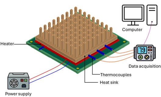
Each prototype is tested using the dedicated testing facility, as shown in Figure 1.
Figure 1: Schematic of the experimental facility for heat sink testing.
The experimental set-up used for evaluating the heat sink performance consists of a DC power supply (i.e. Velleman LABPS3003 30V, 3A), a polyimide-insulated flexible heater (i.e. OMEGA KHLVA-202/40), thermocouples (i.e. K type), a data acquisition system (i.e. NI USB-6210), and a computer for data recording, as shown schematically in Figure 1. A flexible heater is mounted beneath the heat sink, powered by a DC supply to simulate heat generation in microprocessors. Thermocouples are positioned at the heat sink base and calibrated to ASTM E230. A DOWSIL 340 thermal paste layer ensures optimal thermal contact. This enables accurate measurement of the thermal performance of fabricated heat sinks under controlled heat flux conditions.
Session 4: Data analysis and comparison:
A custom LabVIEW interface is developed to acquire, visualise, and log temperature and power data in real time, thereby providing a digital bridge between the physical test rig and the data analysis environment. Temperature and power data are acquired using LabVIEW with the NI USB-6210 DAQ card.
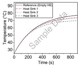
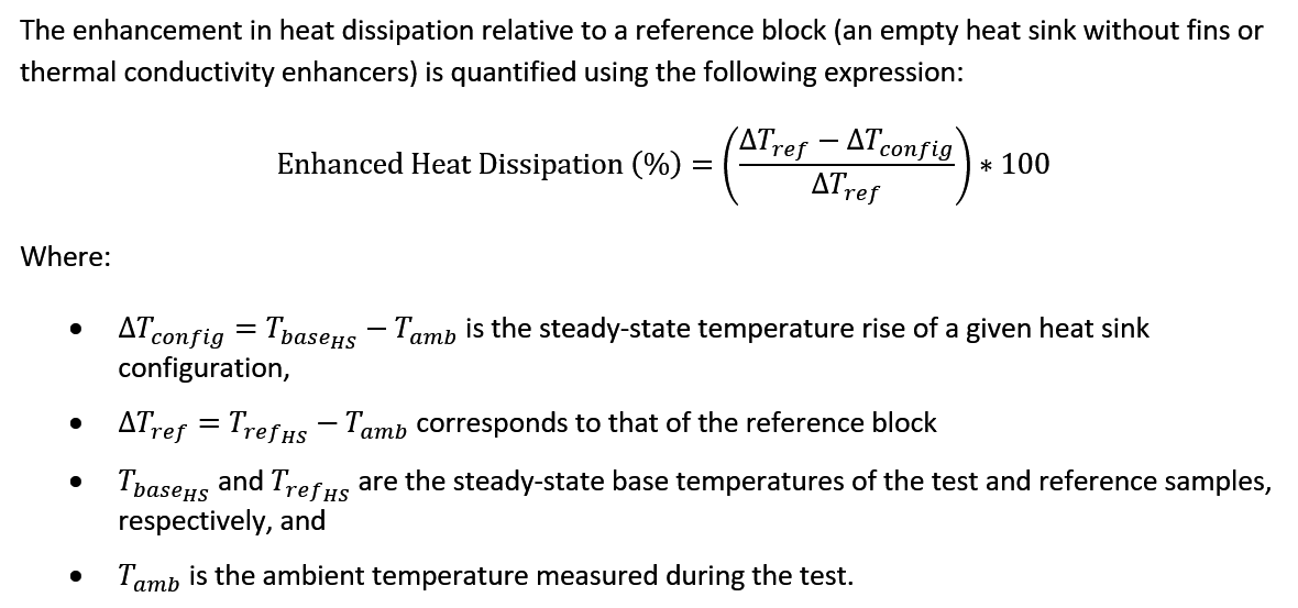
The evaluation and comparison of thermal performance among heat sink geometries designed by various student groups are conducted by recording the base temperature of each configuration as a function of time under a constant heat flux and identical ambient conditions. The transient temperature response, illustrated in Figure 2 (a), provides insight into the rate at which each design approaches steady state, whereas the steady-state base temperature indicates its overall heat dissipation capability. This procedure can be applied to any heat sink to assess and compare its thermal behaviour.
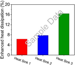
Figure 2: (a) Transient base temperature variation with time for the reference and three heat sink configurations. (b) Enhanced heat dissipation relative to the reference block, illustrating the method used to compare thermal performance across different designs.
Students compare results and interpret the impact of geometry on heat dissipation. They connect observed variations to systemic dependencies between design, manufacture, and experimental performance.
The computed enhancement values, shown in Figure 2 (b) allow direct comparison of heat dissipation efficiency among the different designs. By examining both the temperature–time response and the enhancement ratio, the effect of geometric modification on thermal performance can be quantitatively assessed within a unified experimental framework.
The experimental facility thus forms a closed digital loop connecting design, fabrication, and performance evaluation. The data acquired through LabVIEW and the DAQ system feed back into the design process, enabling iterative optimisation of heat-sink geometry and thermal-management strategies.
Session 5: Reflection:
Teams map out interdependencies between process variables, performance metrics, and uncertainties. They construct feedback diagrams (flowcharts) using Microsoft PowerPoint SmartArt, linking design iterations, measurements, and outcomes to identify emergent system behaviour.
Assessment and reflection:
The assessment can comprise a reflective report and a presentation.
Reports should include:
Interpretation of experimental data and comparison of thermal performance across designs.
Evaluation of system feedback mechanisms, showing how design decisions influenced outcomes.
Discussion of uncertainty management, including:
Identifying sources of uncertainty (e.g. measurement errors, material properties, environmental conditions).
Explaining how these uncertainties were considered during design iterations and testing.
Reflecting on strategies to mitigate uncertainty (e.g. calibration, repeated trials, simulation validation).
Considering the impact of uncertainty on decision-making and overall system performance.
Presentations should summarise:
The design evolution and rationale for changes.
System mapping to illustrate interdependencies and feedback loops.
Insights into complex systems behaviour, including how uncertainty shaped design choices.
Additional image:Heatsink fabricated using a metal 3D printer.
Any views, thoughts, and opinions expressed herein are solely that of the author(s) and do not necessarily reflect the views, opinions, policies, or position of the Engineering Professors’ Council or the Toolkit sponsors and supporters.
You can now view the recording of the official launch webinar for the EPC’s new Complex Systems Toolkit, supported by Quanser. The webinar was live on Tuesday 9th December 2025, 3pm-4.30pm GMT.
To enable closed captions on Vimeo, click the CC button in the video player.
Any views, thoughts, and opinions expressed herein are solely that of the author(s) and do not necessarily reflect the views, opinions, policies, or position of the Engineering Professors’ Council or the Toolkit sponsors and supporters.
Related INCOSE Competencies: Toolkit resources are designed to be applicable to any engineering discipline, but educators might find it useful to understand their alignment to competencies outlined by the International Council on Systems Engineering (INCOSE). The INCOSE Competency Framework provides a set of 37 competencies for Systems Engineering within a tailorable framework that provides guidance for practitioners and stakeholders to identify knowledge, skills, abilities and behaviours crucial to Systems Engineering effectiveness. A free spreadsheet version of the framework can be downloaded.
This resource relates to the Systems Thinking, Systems Modelling and Analysis, Integration, and Technical Leadership INCOSE competencies.
AHEP4 mapping: This resource addresses several of the themes from the UK’s Accreditation of Higher Education Programmes fourth edition (AHEP4): Analytical Tools and Techniques (critical to the ability to model and solve problems), and Integrated / Systems Approach (essential to the solution of broadly-defined problems).
Educational level: Beginner; Intermediate.
Learning and teaching notes:
Modern engineering is increasingly digital, interconnected, and system oriented. To prepare students for this evolving landscape, the Automatic Control Engineering (ACE) Model offers a systems-driven, application-focused framework for practical control engineering education. Developed through a MathWorks-funded project launched in the summer of 2025, the ACE-Model unifies three complementary components that together cultivate systems thinking and model-based systems engineering competence:
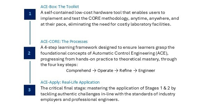
ACE-Box: The Toolkit
ACE-CORE: The Processes
ACE-Apply: Real-World Application
Learners have the opportunity to:
Engage with the entire ACE-CORE (Comprehend – Operate – Refine – Engineer) framework.
Experience a welcoming and accessible introduction to ACE, without an early overemphasis on mathematics. This stands in contrast to the traditional approach, where topics such as Laplace transforms are introduced early on, often creating unnecessary barriers to engagement (Abou-Hayt and Dahl, 2023).
Develop systems awareness and motivation.
Develop confidence, engagement, and curiosity.
Gain the technical knowledge and systems integration mindset required to thrive in the complex, adaptive landscape of digital engineering.
Teachers have the opportunity to:
Introduce control theory topics in a way that addresses the concern of students finding it difficult to link abstract control theory with the world of control engineering practice(Rossiter, 2022; Badau, et al., 2024).
Introduce industry-standard systems processes such as the V-diagram and model-based design workflows.
Progressively link theory to practice.
Support AHEP4 expectations for developing graduates who can apply integrated systems approaches to solving complex problems and the INCOSE Systems Engineering Competency areas of systems thinking, integration, and technical leadership.
What does the ACE-Model consist of?:
Figure 1:The ACE-Model: Integrating the Toolkit (ACE-Box), with the Processes (ACE-CORE), to Lead to the Real-Life Application (ACE-Apply) to build a progressive mastery in Automatic Control Engineering (ACE).
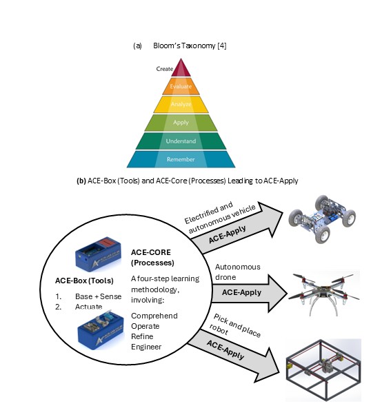
The ACE-Model is closely aligned with Bloom’s Taxonomy, see (Anderson and Krathwohl, 2001)and Figure 2(a) providing a structured pathway for students to progress through the cognitive hierarchy, while developing capabilities across multiple levels of system abstraction. Figure 2(b) offers a schematic view of the three stages of the ACE-Model, as introduced in Figure 1. An initial overview of the ACE-Model is presented here, with further details provided in the following sections.
The ACE-Box is a portable, self-contained hardware tool that brings ACE to life beyond the traditional costly, full-scale laboratories. All that is required is a laptop and the ACE-Box. Designed to support the ACE-CORE methodology, ACE-Box can be set up on a desk, in a classroom, or even at home. MATLAB and Simulink serve as the primary platforms for model-based design, enabling system modelling, control system development, and the deployment of control algorithms to physical hardware (e.g. Arduino Uno) through code generation tools.
ACE-CORE guides learners through successive levels of Bloom’s framework:
Comprehend aligns with Remember and Understand on the Bloom Taxonomy, enabling students to grasp the applications of control engineering before advancing.
Operate corresponds to Apply on the Bloom Taxonomy, as students engage directly with control systems, supported by Stage 2, making use of the ACE-Box (hardware or virtual).
Refine maps to both Analyse and Evaluate on the Bloom Taxonomy, where learners diagnose performance, compare outcomes, and adapt solutions to meet stakeholder requirements.
Engineer extends this process to system-level design and synthesis, making use of modelling and simulation tools such as MATLAB and Simulink. At this stage, students revisit the full cycle (Remember through to Evaluate), but at a higher level of integration with the use of control theory, again supported by the ACE-Box.
At each stage of CORE, learners move from recognising system components to synthesising complex interactions, mirroring the systems engineering lifecycle from requirement capture through verification and validation. This alignment supports AHEP4’s emphasis on analytical and problem-solving competence and INCOSE’s System Definition and Integration competencies.
Finally, learners progress to Create, the highest stage of Bloom’s Taxonomy, by applying their knowledge to design complete control systems for real-world applications such as drones, vehicles, and automation systems. In this way, the ACE-Model scaffolds learning in parallel with Bloom’s progression, from foundational comprehension to advanced problem-solving, design and innovation.
Together, these three pillars form a cohesive learning ecosystem: the toolkit, the process, and the application.
Figure 2:Bloom’s Taxonomy (Anderson and Krathwohl, 2001)(a) and the ACE-Model Three Stages (b).
Collaborative community:
The ACE-Model ‘sits’ within the ACE-Lab, a collaborative community of academics and industry professionals committed to developing, validating, and disseminating open-access systems education resources. The ACE-Lab approach embodies complex adaptive systems principles, where the community evolves through continuous feedback, iteration, and co-design. Membership to the ACE-Lab is open to anyone who shares our vision of advancing control engineering teaching tools and practices. Through this approach, the ACE-Model equips graduates with the knowledge and hands-on skills required to excel in modern ACE careers. Find out more about the ACE-Lab through the following website:www.ace-lab.co.uk
As an evolving community, ACE-Lab continually expands its open-access content through the active contributions of its members. New materials are regularly developed and shared, ensuring the resources remain current and relevant. Through this dynamic, collaborative approach, embodied in the ACE-Model, students not only gain technical knowledge but also develop the capacity to understand, navigate, and work effectively with complex, interconnected engineering systems.
ACE-Box: The toolkit:
The ACE-Box is based on the early development work of Control-Lab-in-a-Box(Pickering, 2023; 2025). CLB integrates sensors, actuators, and microcontroller to allow students to experience dynamic behaviour, and feedback control.
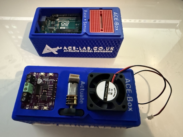
For now, two ACE-Box kits have been developed:
1. Base and sense
2. Actuate
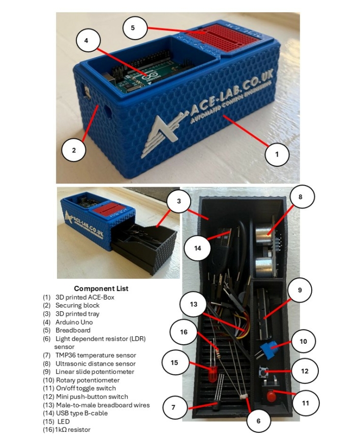
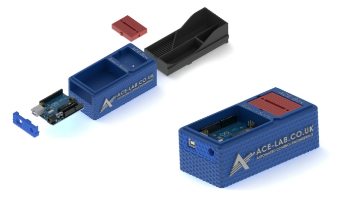
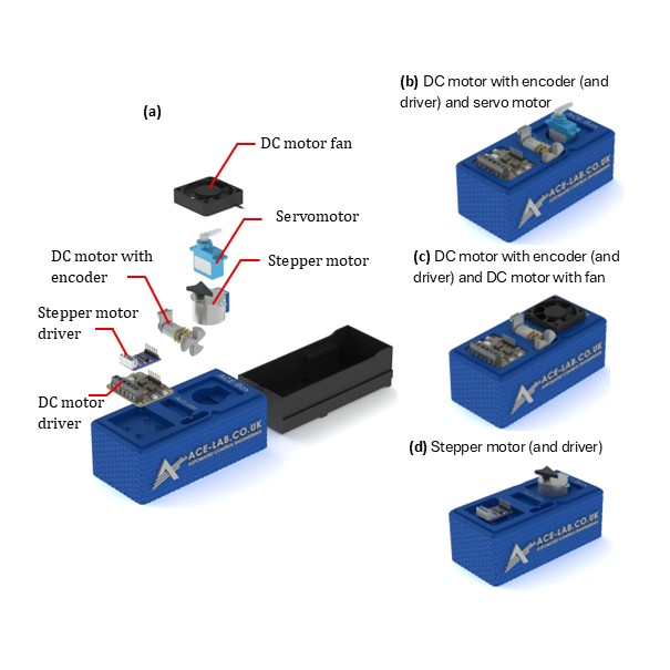
The ACE-Box (base and sense) is illustrated in Figure 3, with the 15 key components labelled, along with an exploded view of the main parts in Figure 4. The ACE-Boxesintegrate the essential microcontrollers, electronics, sensors, and actuators needed to design, implement, and test elements of digital control algorithm development, e.g. control algorithms in real time. It bridges the gap between theory and practice, allowing learners to see how abstract concepts behave in physical systems. The ACE-Box is also available as an open-access resource, with laboratory exercises included, with details provided later in this article. The ACE-Box (labelled (1) in Figure 3) and the tray (labelled (2) in Figure 3) are manufactured using 3D printing, with the necessary files available on the project website referenced above. A list of the required components and their sources is also provided on the project website, corresponding to labels (3) to (15) in Figure 3. Due to the open-source design of ACE-Lab, the library of exercises will continue to expand, supported by contributions from both academia and industry. The ACE-Box (Actuate) is illustrated in Figure 5, with the key actuator components detailed in (a), along with some typical lab set-ups (b, c and d). Figure 6 illustrates both the ACE-Box (Base + Sense) and also ACE-Box (Actuate).
Figure 3:The ACE-Box (Base and Sense).
Figure 4: Assemble of the 3D Printed ACE-Box (Base and Sense).
Figure 5:The ACE-Box (Actuate).
Figure 6:ACE-Box (Actuate) Alongside the ACE-Box (Base + Sense).
ACE-CORE: The methodology:
ACE-CORE is a four-step framework designed to scaffold learning from components to system-of-systems understanding:
Comprehend: Recognise the interdependencies between components within a feedback control system.
Operate: Discover how to operate a control system from understanding system requirements to testing and validation.
Refine: Diagnose, analyse, and optimise performance using feedback principles; students apply system verification and validation approaches.
Engineer: Apply mathematics and modelling to synthesise control algorithms and architectures that achieve desired system behaviours.
The methodology explicitly develops systems thinking, and integrationcompetencies, core to both AHEP4 and INCOSE frameworks.
ACE-CORE is intentionally designed to offer a scaffolded learning experience, allowing students to build confidence step by step as they deepen their understanding. Due to its flexible structure, students can also follow a completely practical route, i.e. avoiding the modelling and simulation. The emphasis is not on rote memorisation of theory, but on progression through understanding the fundamentals of control engineering, e.g. the components that form a feedback control system.These routes enable learners to apply concepts in practical control engineering contexts and develop genuine competence.
ACE-Apply: Real-world application:
ACE-Apply is the project stage, where the skills and knowledge gained from ACE-Box and ACE-CORE are consolidated by tackling authentic challenges aligned with the expectations of industry and professional engineers, see Figure 2(b). At this stage, learners prove their mastery by addressing engineering application problems that reflect the standards of industry practice. The focus is on:
Applying the ACE-CORE methodology to practical control application challenges across domains such as robotics, automotive systems, drones, and industrial automation.
Bridging theory, simulation, and hardware with confidence and agility using industry standard tools and processes.
This stage reinforces AHEP4 Themes 3 and 5, particularly:
Applying integrated systems approaches to complex, real-world problems.
Managing system lifecycle activities including requirements capture, design, testing, and validation.
It also strengthens INCOSE competencies in System Realisation, Integration, and Technical Project Management, encouraging students to act as systems integrators capable of managing interfaces and dependencies across mechanical, electrical, and software domains.
By bridging theory, simulation, and hardware using industry-standard digital tools, ACE-Apply nurtures the ability to navigate complex adaptive systems, anticipate emergent behaviour, and work collaboratively within multidisciplinary engineering ecosystems.
ACE-Box activities:
Upon visiting the ACE-Lab website (www.ace-lab.co.uk), under the tab ‘ACE-Box’, the following tabs exist (with the links provided):
The “What is the ACE-Box?” page introduces educators and students to the ACE-Box platform, outlining its purpose, key features, and practical considerations such as sourcing components and 3D-printing enclosure parts.
The “Prior Exercises” page provides essential onboarding material designed to help users become familiar with MATLAB and Simulink. This includes links to the relevant OnRamp courses, guidance on installing the required software packages, and short tutorial videos that introduce the MATLAB and Simulink graphical user interfaces (GUIs).
The “Base + Sense” section contains a set of introductory tutorial exercises that use the ACE-Box (Base + Sense configuration). These activities help users get started with Simulink code generation for the Arduino Uno, while working with a range of basic sensors and electronic components.
Finally, the “Base + Sense + Actuate” section builds on the previous material by introducing actuation hardware. Using both the Base + Sense and Actuate modules, students and educators learn how to interface with and control devices such as DC motors, servomotors, and stepper motors. This section is designed to familiarise users with actuator integration and reinforce practical control engineering workflows.
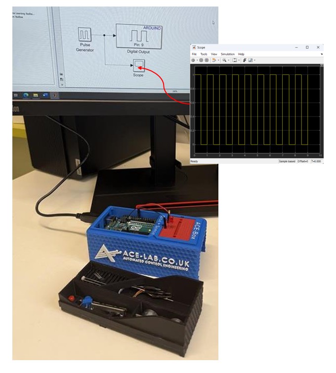
Example use of ACE-Box (Base + Sense):
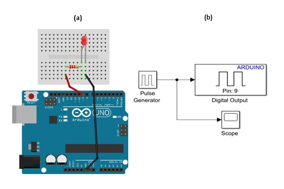
To demonstrate the use of the ACE-Box (Base + Sense), an introductory activity is provided, i.e. the on-off blinking of an LED. Prior to this activity, through ACE-CORE, students should receive a short introduction to microcontrollers covering key concepts such as digital input/output pins, analogue pins, and pulse-width modulation (PWM). Once students are familiar with these fundamentals, they progress to the initial exercise detailed here, which is aligned with defined learning outcomes.
Since MATLAB and Simulink are the primary software tools used with the ACE-Box, students are first guided through installing the Simulink Support Package for Arduino Hardware. After the hardware and software setup is complete, they assemble a simple circuit, see Figure 7(a), and configure a Simulink model for the first exercise, see Figure 6(b). This initial activity requires students to control the state of a digital output pin on the Arduino, switching it on and off. The Simulink model, provided in Figure 7(b), enables students to quickly build the exercise using a visual programming approach. To run the activity, they follow a sequence of steps that includes code generation, which compiles the Simulink model into embedded C code and deploys it onto the Arduino Uno microcontroller. Once completed, the LED connected to the circuit blinks on and off according to the settings of the Simulink pulse generator. A visual of the complete set-up for this initial exercise can be found in Figure 8. At this stage, students are encouraged to experiment with the pulse generator parameters in real-time, observing how changes to the signal properties immediately affect the LED’s behaviour. Scopes can also be used (see Figure 7(b)) to visualise the pulse generator’s square-wave output, including its amplitude, period, and pulse width. This hands-on interaction reinforces the link between the initial set-up and hardware implementation while deepening their understanding of microcontrollers.
Figure 7:LED Simple Circuit (a) and Simulink for Code Generation for the on-off Blinking of an LED.
Figure 8:LED Simple Circuit Set-Up using Simulink for Code Generation for on-off Blinking of an LED.
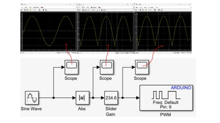
The initial exercise is designed to familiarise students with the ACE-Box and the use of Simulink’s code generation tools. This type of activity is typical for introducing students to a new software and hardware environment. The next exercise involves using pulse width modulation (PWM) to vary the brightness of the LED. This exercise involves using additional blocks in Simulink, see Figure 8, where multiple scopes are used to visualise the signals in real-time. Once students understand the fundamental building blocks of Simulink, they can quickly progress to developing feedback control systems that meet a variety of application requirements. In the authors’ view, student familiarity with Simulink makes it a more accessible platform for designing advanced control algorithms, particularly when working with sub-systems.
Figure 9:LED Simple Circuit Set-Up using Simulink for Code Generation Varying Brightness of an LED using Pulse Width Modulation (PWM).
Building on this foundation, a wide range of laboratory exercises can be developed using the electronic components involved in ACE-Box (Base + Sense), as illustrated in Figure 3, with the option to expand further by incorporating additional components. Examples of extended exercises include:
Analogue sensing and calibration with a temperature sensor
LDR characterisation and linearisation using a voltage divider
Analogue sensing and calibration with a potentiometer sensor
Digital sensing using an ultrasonic sensor
Distance-reactive LED control with proportional feedback (human-in-the-loop plant)
Closed-loop brightness control using LDR feedback and LED PWM
LED–LDR plant control experiments
In addition to sensing activities, the ACE-Box (Actuate) provides four actuators: a servomotor, a DC motor with encoder, a stepper motor, and a DC motor fan. This unit can be used independently or in combination with the Base and Sense ACE-Box to enable more advanced control experiments, such as DC motor speed control or motor control based on light intensity measurements from an LDR.
The flexibility of the ACE-Box system ensures that the number of possible exercises is effectively unlimited, as new experiments can be designed by combining existing sensors and actuators or by integrating additional measurement devices. This also allows unique coursework assignments to be created.
Summary:
The ACE-Model provides a systemic and holistic framework for practical control engineering education that:
Fosters systems thinking and model-based design literacy aligned with INCOSE and AHEP4 competencies.
Connects abstract control theory to complex, real-world systems through accessible hands-on experiences.
Encourages progression from component-level comprehension to system integration.
Builds confidence and motivation through authentic engagement with digital and physical systems, preparing graduates for engineering practice in a complex, interconnected world.
Acknowledgements:
Dr James E. Pickering gratefully acknowledges the support from MathWorks, whose funding made this project possible. He also extends his sincere thanks to Hari Sudeskkumar for his exceptional engineering design contributions and 3D-printing work. The authors would like to thank the Project Advisory Group (PAG) for their valuable guidance throughout the development of this work.
References:
Abou-Hayt, I. and Dahl, B., 2023. A Critical Look at the Laplace Transform Method in Engineering Education. IEEE Transactions on Education, 67(4), pp.542-549.
Anderson, L.W. and Krathwohl, D.R., 2001. A taxonomy for learning, teaching, and assessing: A revision of Bloom’s taxonomy of educational objectives: complete edition. Addison Wesley Longman, Inc..
Badau, N.E., Popescu, T.M., Mihai, M., Dulf, E.H. and Muresan, C.I., 2024. Bridging the gap between control theory and practice: From simple controller design to a practical microcontroller implementation. IFAC-PapersOnLine, 58(26), pp.124-129.
Pickering, J.E., 2023. Control-Lab-in-a-Box: Bridging the Gap between Control Theory and Engineering Practice. In UK and Ireland Engineering Education Research Network Conference Proceedings 2023.
Pickering, J.E., 2025. Leveraging Control-Lab-in-Box (CLB) to Teach Control Engineering on Future Vehicle Technologies MSc. IFAC-PapersOnLine, 59(7), pp.31-35.
Rossiter, J.A., 2022. Future trends for a first course in control engineering. Frontiers in Control Engineering, 3, p.956665.
Any views, thoughts, and opinions expressed herein are solely that of the author(s) and do not necessarily reflect the views, opinions, policies, or position of the Engineering Professors’ Council or the Toolkit sponsors and supporters.
The EPC’s Complex Systems Toolkit, supported by Quanser, is an open-access online resource to help engineering educators build complex systems concepts directly into their teaching and prepare future engineers for tomorrow’s challenges.
We would like to ensure that all universities with Engineering departments are aware of the toolkit and able to make use of it. To this end, we’ve produced a pack of resources that can be distributed to relevant departments and staff members such as Engineering department heads, staff and administrators, as well as Vice-Chancellors, Deans, and anyone else who may find our resource useful in teaching or curriculum development.
We would be very grateful if you could share these resources, and encourage you to explore and use them in your teaching.
Our pack of resources to help you present and promote the Complex Systems Toolkit contains the following files, and can be downloaded individually below, or as a pack from here.
If you have any questions or comments about this resource, please contact Wendy Attwell.
Any views, thoughts, and opinions expressed herein are solely that of the author(s) and do not necessarily reflect the views, opinions, policies, or position of the Engineering Professors’ Council or the Toolkit sponsors and supporters.
Media release
Release date: 1st December 2025
New toolkit helps tomorrow’s engineers understand complex systems
A new, free resource, launched today by the Engineering Professors’ Council, will provide an open-access online toolkit to help engineering educators build complex systems concepts directly into their teaching and prepare future engineers for tomorrow’s challenges.
The Complex Systems Toolkit, created by the Engineering Professors’ Council (EPC) in partnership with Quanser, helps engineers to learn to tackle an increasing range of factors that interact in unpredictable ways. This fills a critical gap in traditional engineering education, where students tended to learn subjects in controlled and isolated conditions.
The new toolkit gives educators a set of resources to teach students to understand and design systems that are not only technically sound, but also resilient, trustworthy, and ethically robust. This involves learning to analyse, model and navigate complexity, to collaborate across disciplines, and to manage complex technical and sociotechnical systems.
It is not just students who benefit. Learning how to integrate complex systems in engineering also supports educators in their own professional development, since many may themselves never have been taught the necessary knowledge, skills, and mindsets that they are now expected to teach.
The Complex Systems Toolkit solves these challenges with a suite of guidance articles, teaching materials and case studies helping to build essential competencies for future engineers, in order to ensure a safer and more equitable world.
Integrating complex systems into engineering teaching aligns with professional standards and accreditation requirements, and also complements institutional goals around interdisciplinarity, sustainability and EDI, allowing the UK to position itself as a leader in engineering education that enables people and the planet to thrive.
The development of the Toolkit was guided by a Working Group comprised of experts from academia, industry and professional bodies. They have worked to produce a toolkit, rooted in educational best practice, that is aligned with the UK Engineering Council’s Accreditation of Higher Education Programmes (AHEP) criteria (the conditions for courses to receive professional accreditation) as well as addressing competencies outlined by the International Council on Systems Engineering (INCOSE).
The Toolkit features advice to educators who want to teach complex systems but are not sure where to begin, as well as ready-to-use classroom resources including case studies and activities that highlight current and emerging real-world issues and can be used and adapted by anyone.
Dr. Nikita Hari, Head of the Teaching and Research Design Support Group at the Department of Engineering Science, University of Oxford, and Working Group Co-Chair comments: “Engineering graduates of today are expected to design climate-resilient cities, ethically deploy AI, and weave circular-economy thinking into supply chains – and all this lives squarely in the messy realm of complex systems. Yet most engineering curricula still treat complexity as an afterthought or a niche elective. This is often misunderstood, misrepresented, or purely ignored, relegating complexity to a footnote.
“The Engineering Professors’ Council’s Complex Systems Toolkit is our academic response, aiming to bridge this gap: a freely accessible, peer-reviewed, resource hub where academics can find, curate and share ready-to-teach resources, assessment blueprints and real-world case studies mapped to AHEP learning outcomes.”
Paul Gilbert, CEO of Quanser, adds: “At Quanser, our mission has always been to help educators bring authentic, system-level engineering experiences to their students. Partnering with the EPC on the Complex Systems Toolkit is a unique opportunity to extend that mission in a way that truly scales. This Toolkit brings academic insight and practical, real-world systems thinking together in a way that empowers educators everywhere. I’m proud of what we’ve created together, and even more excited for how it will help shape the next generation of engineers to thrive in a world defined by complexity.”
Quanser is a world leader in the design and development of cutting-edge solutions that form an interdisciplinary ecosystem for engineering education and research.
Please get in touch for further information, or enquiries about interviews, features or workshops.
 We are seeking further contributions for the Complex Systems Toolkit. Please register your interest in developing a resource by 12th July 2026. You can also join our forthcoming CPD-certificated webinar on ACE-Box and agentic engineering workflows, where we will tell you more about this call for content.