![]() Toolkit: Complex Systems Toolkit.
Toolkit: Complex Systems Toolkit.
Author: Dr. Zareena Gani (University College London); Mohammed Alabdullatif, (University College London).
Topic: Designing and evaluating additively manufactured heat sinks: A systems approach to digital manufacturing.
Title: Teaching complex systems in advanced manufacturing.
Resource type: Teaching activity.
Relevant disciplines: Mechanical engineering; Production and manufacturing engineering.
Keywords: Additive manufacturing; Prototype evaluation; LabVIEW; Data acquisition; Systems thinking.
Licensing: This work is licensed under a Creative Commons Attribution-ShareAlike 4.0 International License.
Downloads: A PDF of this resource will be available soon.
Related INCOSE Competencies: Toolkit resources are designed to be applicable to any engineering discipline, but educators might find it useful to understand their alignment to competencies outlined by the International Council on Systems Engineering (INCOSE). The INCOSE Competency Framework provides a set of 37 competencies for Systems Engineering within a tailorable framework that provides guidance for practitioners and stakeholders to identify knowledge, skills, abilities and behaviours crucial to Systems Engineering effectiveness. A free spreadsheet version of the framework can be downloaded.
AHEP4 mapping: This resource addresses several of the themes from the UK’s Accreditation of Higher Education Programmes fourth edition (AHEP4): Analytical Tools and Techniques (critical to the ability to model and solve problems), and Integrated / Systems Approach (essential to the solution of broadly-defined problems).
Educational level: Intermediate; Advanced.
Learners have the opportunity to:
- Apply systems engineering principles to understand interdependencies between design, manufacturing, and performance.
- Use CAD software (e.g. Autodesk Fusion 360) to model and iterate heat sink designs for additive manufacturing.
- Explore simulation tools such as Thermal Analysis (Fusion 360) for predicting performance before fabrication.
- Engage in design–build–test cycles, fabricating prototypes using metal additive manufacturing and evaluating them experimentally.
- Collect and analyse real-time data using LabVIEW and data acquisition systems, linking digital design to physical performance.
- Develop collaborative and communication skills through team-based design projects and peer review sessions.
- Reflect on sustainability considerations in advanced manufacturing processes.
Teachers have the opportunity to:
- Introduce students to complex systems thinking through practical, problem-based, experiential learning activities.
- Demonstrate the integration of digital tools and physical testing in a closed-loop design process.
- Guide learners in using industry-standard software for design and simulation, reinforcing professional practice.
- Facilitate iterative design processes, encouraging students to analyse trade-offs and optimise performance.
- Incorporate structured prompts, rubrics, and feedback mechanisms to support critical thinking and design evaluation.
- Promote reflection and uncertainty management as part of assessment, linking technical outcomes to systemic insights.
- Align activities with INCOSE competencies and AHEP4 themes, ensuring relevance to accreditation and professional standards.
- Foster peer learning and collaboration through group work and discussion-based sessions.
Materials and tools required:
This activity utilises both computational design tools and an experimental thermal testing facility to establish a complete system feedback loop:
- CAD software (Autodesk Fusion 360) for 3D modelling and design iteration.
- Additive manufacturing equipment (metal 3D printer) for prototype fabrication.
- Thermal Analysis Tool (Fusion 360) or other CFD simulation software (optional – for design simulation).
- Data acquisition system and testing equipment.
The experimental facility integrates the following components:
- DC Power Supply: Velleman LABPS3003 (30V, 3A).
- Polyimide insulated flexible heater: OMEGA KHLVA-202/40.
- K-type thermocouples calibrated to ASTM E230 (0–100°C, ±1°C).
- Data Acquisition System: NI USB-6210 with custom LabVIEW interface.
- Thermal paste: DOWSIL 340 for improved thermal contact.
- Computer interface for real-time data recording and analysis.
Learning and teaching resources:
Pre-reading includes literature on additive manufacturing, design for manufacture, and systems thinking in engineering. Students can review the references listed below to learn the fundamentals of heat sinks, guidance on heat sink design, and important considerations.
- Heat sinks:
- Additive manufacturing:
- Other:
Overview:
This teaching activity introduces students to complex systems thinking by having them design, fabricate, and experimentally evaluate additively manufactured heat sinks. It can form part of an advanced manufacturing module, in which learners apply systems engineering principles to understand the interdependencies among design, manufacturing, and performance. The activity demonstrates how complex systems principles—such as feedback, emergence, and uncertainty—manifest in physical engineering systems. Students are guided to see the design–test–evaluate cycle as an iterative, data-driven process that links digital design environments with real-world performance outcomes.
Activity description:
The experiential learning activity links digital design, manufacturing, and physical evaluation using a complex systems framework. Students iterate designs, fabricate prototypes, and measure thermal performance, reflecting on interdependencies and feedback loops.
Session 1: Introduction:
Students are introduced to complex systems and additive manufacturing principles. Variables affecting heat sink performance – geometry, material, surface finish – are identified. The session frames these variables as part of an interconnected thermal management system.
Notes for educators:
-
- Discuss the role of thermal management in high-performance systems.
- Provide resources (journal articles, books) for further reading.
- Map out factors affecting heat sink efficiency and their systemic relationships, along with the limitations in additive manufacturing.
- Introduce complex design thinking concepts, including feedback loops, trade-offs, and uncertainty.
- Provide an overview of digital tools (e.g. CAD and simulation software) that support iterative design.
Session 2*: Design and manufacture:
Teams create CAD models in Fusion 360 and prepare designs for metal additive manufacturing. Students analyse trade-offs between thermal performance, printability, and material efficiency, applying complex design thinking to balance competing requirements. Feedback from earlier simulations informs iterative design refinement.
Notes for educators:
-
- Prerequisite knowledge:
Students are expected to be familiar with additive manufacturing processes, including basic 3D printing principles and design-for-manufacture considerations. This ensures that the session focuses on systems thinking and optimisation rather than on manufacturing fundamentals.
- Prerequisite knowledge:
-
- Provide design constraints:
Clearly state the size limitations for the heat sink and the capacity of the metal 3D printer, including:
- Provide design constraints:
-
-
- Maximum build volume (e.g. 100 mm × 100 mm × 50 mm).
- Minimum wall thickness (e.g. 1.5 mm).
- Minimum spacing between fins (e.g. 2 mm).
-
Provide a design prompt (e.g. “Optimise heat sink geometry for maximum heat dissipation under given constraints”).
Share an evaluation rubric that assesses the following: design rationale, manufacturability, thermal performance, and discussion/reflection, including consideration of environmental and societal impacts.
Encourage peer-review sessions in which teams critique one another’s designs before fabrication.
*Advanced option:
Academics may incorporate Thermal Analysis Tools within Fusion 360 or CFD simulations (e.g. ANSYS Fluent) to evaluate design performance and refine heat sink geometry for optimal efficiency.
Session 3: Experimental set-up and evaluation:
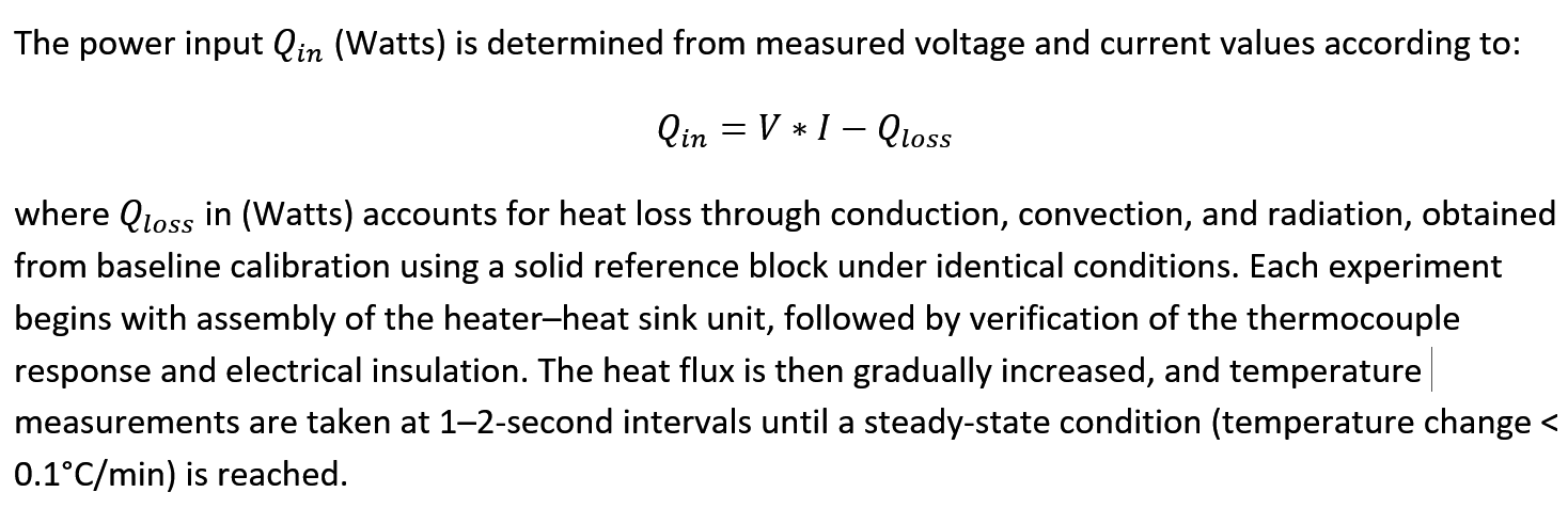
Each prototype is tested using the dedicated testing facility, as shown in Figure 1.
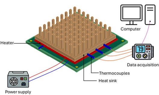
Figure 1: Schematic of the experimental facility for heat sink testing.
The experimental set-up used for evaluating the heat sink performance consists of a DC power supply (i.e. Velleman LABPS3003 30V, 3A), a polyimide-insulated flexible heater (i.e. OMEGA KHLVA-202/40), thermocouples (i.e. K type), a data acquisition system (i.e. NI USB-6210), and a computer for data recording, as shown schematically in Figure 1. A flexible heater is mounted beneath the heat sink, powered by a DC supply to simulate heat generation in microprocessors. Thermocouples are positioned at the heat sink base and calibrated to ASTM E230. A DOWSIL 340 thermal paste layer ensures optimal thermal contact. This enables accurate measurement of the thermal performance of fabricated heat sinks under controlled heat flux conditions.
Session 4: Data analysis and comparison:
A custom LabVIEW interface is developed to acquire, visualise, and log temperature and power data in real time, thereby providing a digital bridge between the physical test rig and the data analysis environment. Temperature and power data are acquired using LabVIEW with the NI USB-6210 DAQ card.
The evaluation and comparison of thermal performance among heat sink geometries designed by various student groups are conducted by recording the base temperature of each configuration as a function of time under a constant heat flux and identical ambient conditions. The transient temperature response, illustrated in Figure 2 (a), provides insight into the rate at which each design approaches steady state, whereas the steady-state base temperature indicates its overall heat dissipation capability. This procedure can be applied to any heat sink to assess and compare its thermal behaviour.
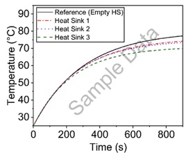
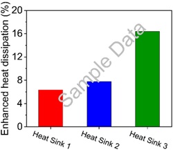
Figure 2: (a) Transient base temperature variation with time for the reference and three heat sink configurations. (b) Enhanced heat dissipation relative to the reference block, illustrating the method used to compare thermal performance across different designs.
Students compare results and interpret the impact of geometry on heat dissipation. They connect observed variations to systemic dependencies between design, manufacture, and experimental performance.
The computed enhancement values, shown in Figure 2 (b) allow direct comparison of heat dissipation efficiency among the different designs. By examining both the temperature–time response and the enhancement ratio, the effect of geometric modification on thermal performance can be quantitatively assessed within a unified experimental framework.
The experimental facility thus forms a closed digital loop connecting design, fabrication, and performance evaluation. The data acquired through LabVIEW and the DAQ system feed back into the design process, enabling iterative optimisation of heat-sink geometry and thermal-management strategies.
Session 5: Reflection:
Teams map out interdependencies between process variables, performance metrics, and uncertainties. They construct feedback diagrams (flowcharts) using Microsoft PowerPoint SmartArt, linking design iterations, measurements, and outcomes to identify emergent system behaviour.
Assessment and reflection:
The assessment can comprise a reflective report and a presentation.
Reports should include:
-
- Interpretation of experimental data and comparison of thermal performance across designs.
-
- Evaluation of system feedback mechanisms, showing how design decisions influenced outcomes.
-
- Discussion of uncertainty management, including:
- Identifying sources of uncertainty (e.g. measurement errors, material properties, environmental conditions).
- Explaining how these uncertainties were considered during design iterations and testing.
- Reflecting on strategies to mitigate uncertainty (e.g. calibration, repeated trials, simulation validation).
- Considering the impact of uncertainty on decision-making and overall system performance.
- Discussion of uncertainty management, including:
Presentations should summarise:
-
- The design evolution and rationale for changes.
- System mapping to illustrate interdependencies and feedback loops.
- Insights into complex systems behaviour, including how uncertainty shaped design choices.
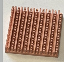
Additional image: Heatsink fabricated using a metal 3D printer.
Any views, thoughts, and opinions expressed herein are solely that of the author(s) and do not necessarily reflect the views, opinions, policies, or position of the Engineering Professors’ Council or the Toolkit sponsors and supporters.