In November 2025 the EPC, with support from Quanser, launched a new Complex Systems Toolkit, aimed at providing accessible, practical resources for embedding complex systems concepts into engineering education.
The Toolkit launched with an abundance of resources, allowing educators and industry professionals to dive into the ‘what’ and ‘how’ of complex systems with knowledge and guidance articles, discover ready-to-use teaching resources including case studies and other classroom activities, and hear directly from the creators and partners who helped shape the Toolkit with a well-attended launch webinar (now available to watch on demand).
These resources have been well used in their first six months, but we’re not stopping there. We want to add further resources, on topics that are emerging as being of vital importance to students as they graduate and seek work. The first of the topics that we want to cover is intelligent robotics.
What and why?
Intelligent robotics, and the more recent applications to physical AI, generally refers to artificial intelligence systems that are embedded in and interact directly with the physical world, rather than operating purely in digital environments. This includes technologies like robots, autonomous vehicles, and drones that can perceive their surroundings through sensors, process that information using AI models, and take real-world actions. Unlike traditional software-based AI, intelligent robotics applications deal with real-time constraints, uncertainty, and complex environments, requiring tight integration between hardware (like sensors and actuators) and decision-making algorithms.
For engineering students, learning about intelligent robotics and physical AI workflows matters because it sits at the intersection of software, hardware, and real-world problem solving. It forces students to grapple with uncertainty, noisy sensor data, timing constraints, and safety considerations, which are unavoidable in real systems like robots or autonomous vehicles. That experience builds practical intuition about how algorithms behave outside ideal conditions. Engineers who understand this are better equipped to design systems that are robust, adaptive, and resilient. Industries are moving rapidly toward automation, robotics, and intelligent infrastructure, so familiarity with intelligent robotics and physical AI workflows opens doors in fields like manufacturing, healthcare technology, and transportation. It helps engineers think holistically: not just “does the code work?” but “does the system behave safely and effectively in the real world?”.
Contributors sought to develop resources on Intelligent Robotics for inclusion in the toolkit
We are seeking experts in intelligent robotics, from academia, industry, and engineering organisations, to develop resources on this topic for publication in the Complex Systems Toolkit. These resources will inform, guide and aid educators to embed teaching on intelligent robotics into their engineering lessons, modules or courses.
We invite contributors to develop resources in three areas:
Knowledge articles: These are resources that users can access to improve their knowledge or find more information. These are intended to provide theoretical and practical background on intelligent robotics concepts and tools such as modelling or decision-making approaches. While guidance articles focus on “how”, knowledge articles focus on “what”.
Guidance articles: These are resources that users can access to learn how to do something. These are intended to provide practical advice on subjects such as how to explain intelligent robotics to students, or how to assess for skills and competencies in this area. While knowledge articles focus on “what”, guidance articles should focus on “how”.
Teaching activities: These are resources that users can access to help them know what to integrate and implement. These include use cases/case studies which provide examples of intelligent robotics which can be directly utilised in teaching with the suggested tools, as well as other classroom activities such as coursework, project briefs, lesson plans, demonstration simulations, or other exercises.
We’re also looking for experts in intelligent robotics and physical AI to join us as reviewers and working group members.
We are seeking content on the following topics
Resources should reference the topic’s relationship to complex systems and engineering education/graduate skills. We are particularly interested in resources that help engineering educators teach these topics effectively.
Robotics and autonomous systems
Human-robot interaction
Swarm systems and distributed intelligence
Edge AI and embedded intelligence
Cyber-physical systems
Simulation and digital twins
Safety, resilience, and uncertainty
Systems thinking for Intelligent Robotics or Physical AI
Teaching approaches and assessment methods
Read more about the specific content we are looking for (click on the arrows to expand the sections)
Submit a knowledge article
Submit a knowledge article
As well as choosing a topic, you will need to choose an angle for your resource.
For knowledge articles. contributors might consider one of the following:
What it is: explaining the topic and its relation to complex systems.
Why educators should teach it / students should learn it.
Why it should be integrated into engineering education.
An angle of your own choosing.
These articles should connect the why (why must teaching about the topic be present in engineering education?) to the how (how can this be done efficiently and effectively?). Through these tools, we aim to help upskill UK engineering educators so that they feel capable of and confident in integrating complex systems concepts and intelligent robotics topics into their engineering teaching.
Step 1: Read the guidance for submitting a knowledge article
Research:
Knowledge articles are resources that users can access to improve their knowledge or find more information. These are intended to provide theoretical and practical background on complex systems concepts and tools such as modelling or decision-making approaches. While guidance articles focus on “how”, knowledge articles focus on “what”.
Knowledge articles are meant to be overviews that a reader with no prior knowledge of the topic could refer to in order to develop a baseline understanding and learn where to look for additional information (they can reference other sources). They should be understandable to students as well: imagine that an educator might excerpt content from the article to provide their students context on a project or learning activity.
They should be approximately 500-1000 words (although they can be more in depth if necessary) and reference relevant online open-source resources.
Overview:
The articles are meant to be able to stand on their own as a piece of knowledge on a topic; they are also meant to work alongside other articles so that taken together they form a sort of complex systems in engineering handbook.
Purpose:
Each article should inform, explain, and provide knowledge on the topic. Put yourself in the perspective of an engineering educator who is new to the topic.
Content:
The content of the article should be organised and well developed. That is, it should be presented in a logical way and thoroughly explained.
References and resources:
Where additional explanation could be given, it might point to other resources, and where information is presented from another source, it needs to be properly referenced using Harvard referencing.
Format:
Knowledge articles should follow this format:
Premise;
Body of article, divided up into headed sections as necessary;
Knowledge articles should be submitted in Word file format (.doc or .docx).
Also submit any additional resources such as spreadsheets, handouts etc., and ensure that they are in an editable format. Please clarify where in the resource these should be embedded or linked.
Any corresponding images should be submitted in either .jpeg, .jpg or .png format. We need these to be uploaded separately from the Word file, as we will be embedding them in a web page. Please ensure that they are of high resolution and adequate size (we suggest a minimum of 800 pixels wide); that you have the right or permission to use them (bearing in mind they will be published under a Creative Commons license); and that you have added any permissions, sources, credits or other details for them in the body of the document that you are submitting.
To ensure that everyone can use and adapt the Toolkit resources in a way that best fits their teaching or purpose, this work will be licensed under a Creative Commons Attribution-ShareAlike 4.0 International License. Under this licence users are free to share and adapt this material, under terms that they must give appropriate credit and attribution to the original material and indicate if any changes are made.
These articles should also connect the why (why must teaching about this topic be present in engineering education?) to the how (how can this be done efficiently and effectively?). Through these tools, we aim to help upskill UK engineering educators so that they feel capable of and confident in integrating complex systems concepts and intelligent robotics topics into their engineering teaching.
Step 1: Read the guidance for submitting a guidance article
Research:
Guidance articles are resources that users can access to learn how to do something. These are intended to provide practical advice on subjects such as how to explain complex systems to students, or how to assess for skills and competencies in complex systems. While knowledge articles focus on “what”, guidance articles should focus on “how.”
Guidance articles aim to help situate our teaching resources in an educational context and to signpost to additional research and resources on complex systems theory and tools.
They should be approximately 500-1000 words (although they can be more in depth if necessary) and reference relevant online open-source resources.
Overview:
Guidance articles are meant to be able to stand on their own as a piece of guidance on a topic; they are also meant to work alongside other articles so that taken together they form a sort of complex systems in engineering handbook.
Purpose:
Each article should inform, explain, and provide guidance on the topic. Put yourself in the perspective of an engineering educator who is new to the topic.
Content:
The content of the article should be organised and well developed. That is, it should be presented in a logical way and thoroughly explained.
References and resources:
Where additional explanation could be given, it might point to other resources, and where information is presented from another source, it needs to be properly referenced using Harvard referencing.
Format:
Guidance articles should follow this format:
Premise;
Body of article, divided up into headed sections as necessary;
Guidance articles should be submitted in Word file format (.doc or .docx).
Also submit any additional resources such as spreadsheets, handouts etc., and ensure that they are in an editable format. Please clarify where in the resource these should be embedded or linked.
Any corresponding images should be submitted in either .jpeg, .jpg or .png format. We need these to be uploaded separately from the Word file, as we will be embedding them in a web page. Please ensure that they are of high resolution and adequate size (we suggest a minimum of 800 pixels wide); that you have the right or permission to use them (bearing in mind they will be published under a Creative Commons license); and that you have added any permissions, sources, credits or other details for them in the body of the document that you are submitting.
To ensure that everyone can use and adapt the Toolkit resources in a way that best fits their teaching or purpose, this work will be licensed under a Creative Commons Attribution-ShareAlike 4.0 International License. Under this licence users are free to share and adapt this material, under terms that they must give appropriate credit and attribution to the original material and indicate if any changes are made.
As well as choosing a topic, you will need to choose an angle for your resource.
For activities, contributors might consider one of the following:
Case studies that, through a real-world situation, illustrate the topic and its relation to complex systems, use cases for the tools that can be used to model / simulate this, techniques that promote development and use of systems architecture, and effects such as trade-offs, emergent properties, impacts, or unintended consequences. Case studies could also reference the implications for risk, security, ethics, sustainability, teamwork, and communication.
Demonstrator simulations that provide examples of how systems can be modelled.
This could include:
Examples of how the topic relates complex systems
Interactive examples showing how well-intentioned action can lead to failure
Interactive examples showing the best approaches to handling complexity
Teaching/learning activities, coursework, project briefs, lesson plans, modelling or simulation exercise/activities, technical content related to complex systems, worksheets, slides, robotics labs, swarm behaviour activities, system mapping exercises, hardware-in-the-loop demonstrations, digital twin exercises, or other teaching materials.
An angle of your own choosing.
These resources should promote active learning pedagogies and real-world teaching methods by showing how complex systems teaching can be embedded within technical problems and engineering practice. Through these resources, we aim to help upskill UK engineering educators so that they feel capable of and confident in integrating complex systems into their engineering teaching.
Step 1: Read the guidance for submitting a teaching activity/resource
Research:
Teaching activities are resources that users can access to help them know what to integrate and implement. These include use cases/case studies which provide examples of complex systems topics which can be directly utilised in teaching with the suggested tools, as well as other classroom activities such as coursework, project briefs, lesson plans, simulation exercises, robotics labs, swarm behaviour activities, system mapping exercises, hardware-in-the-loop demonstrations, digital twin exercises, or other exercises.
Before you begin, you should review existing Complex Systems Toolkit teaching resources, since we hope that contributions will be fairly consistent in length, style, tone, format and approach. Remember that the audience for these resources is educators seeking to embed complex systems topics within their engineering teaching.
Step 1a: Guidance for submitting a case study
Case studies present real-world scenarios that can be used in teaching about complex systems topics in engineering. They provide students with opportunities to explore complex systems tools, and trade-offs, in authentic contexts, and reflect on decisions made about them.
They are usually based on a real example, although fictionalised cases are acceptable when they are grounded in realistic detail. Case studies should enable students to identify or interpret key features of complex systems topics (feedback loops, interdependence or emergent behaviour) and apply relevant tools or frameworks to make sense of the situation.
Case studies will vary in length depending on scope and resource, but many are around 1500-2000 words. They should reference relevant online open-source resources.
The case study should be presented as a narrative about a complex systems issue in engineering.
Narrative strength: the case should be clearly structured with a compelling and coherent story.
System complexity: it should explore interdependencies, multiple stakeholders and/or competing goals.
Tool integration: systems tools should be mentioned or incorporated (e.g. soft systems methodology, SysML, Agent-based modelling etc).
Activities and Resources: there should be questions, prompts or teaching activities to guide discussion or classroom use.
Authenticity:
Case studies are most effective when they feel like they are realistic, with characters that you can identify or empathise with, and with situations that do not feel fake or staged. Giving characters names and backgrounds, including emotional responses, and referencing real-life experiences help to increase authenticity.
Complexity of issue:
Many cases are either overly complicated so that they become overwhelming, or so straightforward that they can be “solved” quickly. A good strategy is to try to develop multiple dimensions of a case, but not too many that it becomes unwieldy. Additionally, complexity can be added through different parts of the case so that instructors can choose a simpler or more complicated version depending on what they need in their educational context.
Activities and resources:
You should provide a variety of suggestions for discussion points and activities to engage learners, as well as a list of reliable, authoritative open-source online resources, to both help educators prepare and to enhance students’ learning. Where information is presented from another source, it needs to be properly referenced using Harvard referencing.
Educational level and assessment:
Educational level: When writing your case study, you should consider which level it is aimed at. A Beginner level case is aimed at learners who have not had much experience in engaging with this complex systems topic or problem, and usually focuses on only one or two dimensions of a challenge. An Advanced-level case is aimed at learners who have had previous practice in engaging with this complex systems topic or problem, and often addresses multiple challenges. An Intermediate case is somewhere in between.
Assessment: If possible, suggest assessment opportunities for activities within the case, such as marking rubrics or example answers.
Format:
The case study should follow the following format:
Teaching notes (with learning objectives, time needed, materials): This is an overview of the case and its dilemma, and how it relates to AHEP4 and INCOSE competencies.
Learning and teaching resources: A list of reliable, authoritative, open-source online resources that relate to the case and its dilemma. These can be from a variety of sources, such as academic institutions, journals, news websites, business, and so on. We suggest a minimum of five sources that help to provide context to the case and its dilemmas.
Summary of system or context.
Narrative of the case (presenting the complexity).
Questions and activities. This is where you provide suggestions for discussions and activities related to the case and the dilemma.
Further discussion or challenge (optional). Some case studies are sufficiently complex at one dilemma, but if the case requires it you can provide further parts (up to a maximum of three).
Step 1b: Read the guidance for submitting a different teaching activity
Purpose & outcomes:
Teaching activities/tools are intended to support educators’ ability to apply and embed complex systems concepts and topics within their engineering teaching.
Educators need to quickly and easily find help with:
Adapting and integrating existing complex systems resources to their disciplinary context.
Implementing new and different pedagogies that support complex systems learning.
Structuring lessons, modules, and programmes so that complex systems skills and outcomes are central themes.
Thus, these teaching activities/tools will provide crucial guidance for those who may be teaching complex systems related material for the first time, or who are looking for new and different ways to integrate complex systems concepts or topics into their teaching.
Teaching activities/tools may take the form of learning activities, coursework, project briefs, lesson plans, modelling or simulation exercise/activities, technical content related to complex systems, worksheets, slides, robotics labs, swarm behaviour activities, system mapping exercises, hardware-in-the-loop demonstrations, digital twin exercises, or other similar teaching materials.
Imagine that you are an engineering educator who is new to teaching complex systems concepts or topics. You turn to this teaching tool to help you apply and embed these in your module.
Does this resource help introduce or develop concepts related to complex systems or systems thinking so that learners can engage with these topics in the context of engineering?
If not, what is needed to make this possible?
Presentation and clarity:
Depending on the resource, you may choose to provide worksheets, slides, problem sets, narrative prompts, etc.
Is the resource explained in such a way that someone new to teaching complex systems could understand how to use it?
Is the material clearly introduced and described?
Resources and guidance:
Depending on the topic, educators may need additional resources or guidance to support their use of the material. For instance, background information may be required or a technical topic explained.
Have you provided sufficient material so that educators can easily employ the resource?
The teaching activity/tool should follow this format:
Overview:
Short description of what the resource is and what it aims to do.
States how it is related to complex systems or systems thinking topic(s), referring to external content such as INCOSE Competencies and AHEP 4.
Provides an overview of the activity, suggesting how it might be implemented and in what contexts, how long it might take, and any other relevant delivery information.
Details any specific materials or software required for the activity, as well as any modelling or simulation tools to be used.
Lists any learning and teaching resources recommended in order to undertake the activity, including suggested pre-reading or other references.
Explains the activity in as much detail as is required (this will vary depending on the type of material the resource addresses.)
If relevant, provides assessment guidance–marking rubrics, sample answers, etc.
Step 2b: Before you submit, review this checklist:
Does this resource help introduce or develop concepts/topics related to complex systems or systems thinking so that learners can engage with these topics in the context of engineering?
Is the resource explained in such a way that someone new to teaching complex systems could understand how to use it?
Is the material clearly introduced and described?
Have you provided sufficient material so that educators can easily employ the resource?
Step 3: Submitting your teaching activity/resource
Teaching resources should be submitted in Word file format (.doc or .docx).
Also submit any additional resources such as spreadsheets, handouts etc., and ensure that they are in an editable format. Please clarify where in the resource these should be embedded or linked.
Any corresponding images should be submitted in either .jpeg, .jpg or .png format. We need these to be uploaded separately from the Word file, as we will be embedding them in a web page. Please ensure that they are of high resolution and adequate size (we suggest a minimum of 800 pixels wide); that you have the right or permission to use them (bearing in mind they will be published under a Creative Commons license); and that you have added any permissions, sources, credits or other details for them in the body of the document that you are submitting.
To ensure that everyone can use and adapt the Toolkit resources in a way that best fits their teaching or purpose, this work will be licensed under a Creative Commons Attribution-ShareAlike 4.0 International License. Under this licence users are free to share and adapt this material, under terms that they must give appropriate credit and attribution to the original material and indicate if any changes are made.
Please register your interest in developing a resource by12th July 2026. NOTE:This deadline has been extended to 26th July. Apply here.
If you have already registered an interest and we are expecting your submission, the deadline to submit first drafts is 31st August 2026. NOTE: This deadline may be extended for those registering interest after the initial 12th July deadline. Submit your Complex Systems Toolkit Contribution here. Co-authors should complete this form.
We are also seeking experts on intelligent robotics/physical AIto join the Complex Systems Toolkit Working Group. Please apply here.
We are also seeking experts on intelligent robotics/physical AI to review resources for the toolkit. Please apply here.
If you would like to suggest links to pages or online resources that we can add to our database of engineering education resources for complex systems teaching, please email Wendy Attwell.
Additional information
In undertaking this work, contributors will become part of the growing community of educators who are helping to ensure that tomorrow’s engineering professionals have the complex systems skills, knowledge, and attributes that they need to provide a better future for us all. Contributors will be fully credited for their work on any relevant Toolkit materials and will be acknowledged as authors should the resources be published in any form. Developing these resources will provide the chance to work with a dynamic, diverse and passionate group of people leading the way in expanding engineering teaching resources, and may help in professional development, such as preparing for promotion or fellowship.
Any views, thoughts, and opinions expressed herein are solely that of the author(s) and do not necessarily reflect the views, opinions, policies, or position of the Engineering Professors’ Council or the Toolkit sponsors and supporters.
Peter Martin, Director of Research & Development at Quanser, and co-chair of the Complex Systems Toolkit Working Group, reflects on the importance of engineers understanding complex systems when working in the field of intelligent robotics.
“In late 2024 I had the opportunity to join the EPC Complex Systems Toolkit team as co-chair of the working group. At the time I felt a little fraudulent, as the intricacies of complex systems thinking was new to me. I had brushed up against complex systems numerous times over the years as I had studied and worked in the world of robotics for over 20 years. However, I had never discovered the world of formal complex systems analysis. Looking back, this is a perfect validation for the need to create a toolkit to better prepare students for careers like mine. As I have learned more over the last 18 months about the tools and techniques that systems engineers employ to model and manage complexity, the critical value that these techniques offer engineers in the world of intelligent robotics has become obvious. As we hear often in the field of engineering lab equipment for the academic space, “I wish I’d had this when I was at university”.
The other reassuring aspect of my experience, for me, is that I’m not alone. A growing need for better approaches to managing complexity has emerged in industry over the last couple of decades as robotics and their governing systems have become increasingly integrated into society. This transition of robotics out of the structured environment of the factory floor and into direct contact with both the dynamic and unstructured world and the public, has introduced a high degree of non-linear predictability, complex interactions with multiple robotic agents, and emergent behaviours as the decision-making algorithms that dictate robotic behaviour adapt. All of these elements are central to the world of complex systems analysis.
At a high level, modern robotics systems no longer represent technical engineering challenges in the narrow, discipline-specific sense that engineers would traditionally have seen in higher education. They are complex adaptive systems that routinely demonstrate behaviours that emerge from interactions with their environment rather than being fully specified in advance. A robot navigating a hospital corridor, a swarm coordinating warehouse logistics, or a surgical assistant adjusting in real time to tissue variability represent challenges in undefined, non-linear, and largely unpredictable spaces. Students, and later robotics engineers who lack a complex systems vocabulary are essentially tasked with trying to understand emergence without the tools to describe it.
An example that I like to use is one that we encountered a couple of years ago: a team of mobile robots transporting parts around a manufacturing space. In many cases, the agents (ground robots, arms, etc.) in this scenario are programmed with independent control and decision-making code to govern their behaviour, with some overarching supervisory code to manage tasks and assignments. The ground robots would have algorithms to localise, path plan, navigate, and avoid obstacles while communicating with other complementary agents and central task management. However, as I have learned, complexity lies in the emergence of unexpected interactions between the agents and their environment. How they avoid each other and the environment while achieving their tasks is largely a complex non-linear system where conflicts can routinely delay or disrupt their operation. Introducing more sources of disruption such as humans, unstructured environments, weather conditions etc. only makes dealing with unpredictable scenarios more and more complicated using traditional techniques.
Luckily, many of the tools and techniques that are highlighted in the toolkit have direct applications to the challenges faced by engineers in the world of robotics. Causal Loop Diagrams (CLDs) are an excellent way to model the feedback dynamics that are at play in adaptive control systems. When a robot’s perception system updates its world model based on changes in what the sensors can perceive, that leads to changes in its action policy that when executed create a feedback loop. These diagrams are a great way to visualise and analyse these loops. Agent-Based Modelling (ABM) is directly relevant to the scenario I described above where swarms of robot must be coordinated or manage human-robot interaction scenarios. Using these simulation tools, engineers can test and manage emergent fleet behaviour without hardware. If things do go sideways, Fault Tree Analysis is a common approach to mapping causes and evaluating data to help develop robots that work in safety-critical applications. Finally, for long-term operations such as field robotics missions, Systems Dynamics Modelling can be a useful tool for predicting and managing a robot’s resource consumption (battery, compute, bandwidth) depending on the required task performance over time.
In addition to these considerations, there is a whole world of network modelling and the management of behaviour stemming from machine learning and applied AI algorithms that also overlaps quite closely with complex systems. Engineers that understand emergence, feedback loops, and attractors are far better equipped to reason about why a robot does something unexpected, than students who only have a component-driven technical understanding of the behaviour of an intelligent robot. Beyond the decisions, at an actual component level there are critical decisions that need to be made for efficient deployment of physical and edge AI algorithms. What data is processed locally and what goes to the cloud, when models are updated and how decision making is distributed across a robot swarm are exactly the kind of questions that systems thinking trains engineers to answer. Systems tools are ready to help, including influence diagrams to manage information exchange and action planning.
Overall, the field of complex systems introduces a set of tools, techniques, and mental models that are increasingly essential to robotics engineers that seek to prepare their agents to be effective in performing complicated tasks in increasingly complex systems.”
Intelligent robotics, and the more recent applications to physical AI, generally refers to artificial intelligence systems that are embedded in and interact directly with the physical world, rather than operating purely in digital environments. For engineering students, learning about intelligent robotics and physical AI workflows matters because it sits at the intersection of software, hardware, and real-world problem solving. It helps engineers think holistically: not just “does the code work?” but “does the system behave safely and effectively in the real world?”.
We are seeking experts in intelligent robotics, from academia, industry, and engineering organisations, to develop resources on this topic for publication in the Toolkit. These resources will inform, guide and aid educators to embed teaching on intelligent robotics into their engineering lessons, modules or courses.
Any views, thoughts, and opinions expressed herein are solely that of the author(s) and do not necessarily reflect the views, opinions, policies, or position of the Engineering Professors’ Council or the Toolkit sponsors and supporters.
Downloads: A PDF of this resource will be available soon.
Related INCOSE Competencies: Toolkit resources are designed to be applicable to any engineering discipline, but educators might find it useful to understand their alignment to competencies outlined by the International Council on Systems Engineering (INCOSE). The INCOSE Competency Framework provides a set of 37 competencies for Systems Engineering within a tailorable framework that provides guidance for practitioners and stakeholders to identify knowledge, skills, abilities and behaviours crucial to Systems Engineering effectiveness. A free spreadsheet version of the framework can be downloaded.
AHEP4 mapping:This resource addresses several of the themes from the UK’s Accreditation of Higher Education Programmes fourth edition (AHEP4): Analytical Tools and Techniques (critical to the ability to model and solve problems), and Integrated / Systems Approach (essential to the solution of broadly-defined problems).
Educational level: Intermediate; Advanced.
Learners have the opportunity to:
Apply systems engineering principles to understand interdependencies between design, manufacturing, and performance.
Use CAD software (e.g. Autodesk Fusion 360) to model and iterate heat sink designs for additive manufacturing.
Explore simulation tools such as Thermal Analysis (Fusion 360) for predicting performance before fabrication.
Engage in design–build–test cycles, fabricating prototypes using metal additive manufacturing and evaluating them experimentally.
Collect and analyse real-time data using LabVIEW and data acquisition systems, linking digital design to physical performance.
Develop collaborative and communication skills through team-based design projects and peer review sessions.
Reflect on sustainability considerations in advanced manufacturing processes.
Teachers have the opportunity to:
Introduce students to complex systems thinking through practical, problem-based, experiential learning activities.
Demonstrate the integration of digital tools and physical testing in a closed-loop design process.
Guide learners in using industry-standard software for design and simulation, reinforcing professional practice.
Facilitate iterative design processes, encouraging students to analyse trade-offs and optimise performance.
Incorporate structured prompts, rubrics, and feedback mechanisms to support critical thinking and design evaluation.
Promote reflection and uncertainty management as part of assessment, linking technical outcomes to systemic insights.
Align activities with INCOSE competencies and AHEP4 themes, ensuring relevance to accreditation and professional standards.
Foster peer learning and collaboration through group work and discussion-based sessions.
Materials and tools required:
This activity utilises both computational design tools and an experimental thermal testing facility to establish a complete system feedback loop:
CAD software (Autodesk Fusion 360) for 3D modelling and design iteration.
Additive manufacturing equipment (metal 3D printer) for prototype fabrication.
Thermal Analysis Tool (Fusion 360) or other CFD simulation software (optional – for design simulation).
Data acquisition system and testing equipment.
The experimental facility integrates the following components:
K-type thermocouples calibrated to ASTM E230 (0–100°C, ±1°C).
Data Acquisition System: NI USB-6210 with custom LabVIEW interface.
Thermal paste: DOWSIL 340 for improved thermal contact.
Computer interface for real-time data recording and analysis.
Learning and teaching resources:
Pre-reading includes literature on additive manufacturing, design for manufacture, and systems thinking in engineering. Students can review the references listed below to learn the fundamentals of heat sinks, guidance on heat sink design, and important considerations.
This teaching activity introduces students to complex systems thinking by having them design, fabricate, and experimentally evaluate additively manufactured heat sinks. It can form part of an advanced manufacturing module, in which learners apply systems engineering principles to understand the interdependencies among design, manufacturing, and performance. The activity demonstrates how complex systems principles—such as feedback, emergence, and uncertainty—manifest in physical engineering systems. Students are guided to see the design–test–evaluate cycle as an iterative, data-driven process that links digital design environments with real-world performance outcomes.
Activity description:
The experiential learning activity links digital design, manufacturing, and physical evaluation using a complex systems framework. Students iterate designs, fabricate prototypes, and measure thermal performance, reflecting on interdependencies and feedback loops.
Session 1: Introduction:
Students are introduced to complex systems and additive manufacturing principles. Variables affecting heat sink performance – geometry, material, surface finish – are identified. The session frames these variables as part of an interconnected thermal management system.
Notes for educators:
Discuss the role of thermal management in high-performance systems.
Provide resources (journal articles, books) for further reading.
Map out factors affecting heat sink efficiency and their systemic relationships, along with the limitations in additive manufacturing.
Introduce complex design thinking concepts, including feedback loops, trade-offs, and uncertainty.
Provide an overview of digital tools (e.g. CAD and simulation software) that support iterative design.
Session 2*: Design and manufacture:
Teams create CAD models in Fusion 360 and prepare designs for metal additive manufacturing. Students analyse trade-offs between thermal performance, printability, and material efficiency, applying complex design thinking to balance competing requirements. Feedback from earlier simulations informs iterative design refinement.
Notes for educators:
Prerequisite knowledge:
Students are expected to be familiar with additive manufacturing processes, including basic 3D printing principles and design-for-manufacture considerations. This ensures that the session focuses on systems thinking and optimisation rather than on manufacturing fundamentals.
Provide design constraints:
Clearly state the size limitations for the heat sink and the capacity of the metal 3D printer, including:
Maximum build volume (e.g. 100 mm × 100 mm × 50 mm).
Minimum wall thickness (e.g. 1.5 mm).
Minimum spacing between fins (e.g. 2 mm).
Provide a design prompt (e.g. “Optimise heat sink geometry for maximum heat dissipation under given constraints”).
Share an evaluation rubric that assesses the following: design rationale, manufacturability, thermal performance, and discussion/reflection, including consideration of environmental and societal impacts.
Encourage peer-review sessions in which teams critique one another’s designs before fabrication.
*Advanced option:
Academics may incorporate Thermal Analysis Tools within Fusion 360 or CFD simulations (e.g. ANSYS Fluent) to evaluate design performance and refine heat sink geometry for optimal efficiency.
Session 3: Experimental set-up and evaluation:
Each prototype is tested using the dedicated testing facility, as shown in Figure 1.
Figure 1: Schematic of the experimental facility for heat sink testing.
The experimental set-up used for evaluating the heat sink performance consists of a DC power supply (i.e. Velleman LABPS3003 30V, 3A), a polyimide-insulated flexible heater (i.e. OMEGA KHLVA-202/40), thermocouples (i.e. K type), a data acquisition system (i.e. NI USB-6210), and a computer for data recording, as shown schematically in Figure 1. A flexible heater is mounted beneath the heat sink, powered by a DC supply to simulate heat generation in microprocessors. Thermocouples are positioned at the heat sink base and calibrated to ASTM E230. A DOWSIL 340 thermal paste layer ensures optimal thermal contact. This enables accurate measurement of the thermal performance of fabricated heat sinks under controlled heat flux conditions.
Session 4: Data analysis and comparison:
A custom LabVIEW interface is developed to acquire, visualise, and log temperature and power data in real time, thereby providing a digital bridge between the physical test rig and the data analysis environment. Temperature and power data are acquired using LabVIEW with the NI USB-6210 DAQ card.
The evaluation and comparison of thermal performance among heat sink geometries designed by various student groups are conducted by recording the base temperature of each configuration as a function of time under a constant heat flux and identical ambient conditions. The transient temperature response, illustrated in Figure 2 (a), provides insight into the rate at which each design approaches steady state, whereas the steady-state base temperature indicates its overall heat dissipation capability. This procedure can be applied to any heat sink to assess and compare its thermal behaviour.
Figure 2: (a) Transient base temperature variation with time for the reference and three heat sink configurations. (b) Enhanced heat dissipation relative to the reference block, illustrating the method used to compare thermal performance across different designs.
Students compare results and interpret the impact of geometry on heat dissipation. They connect observed variations to systemic dependencies between design, manufacture, and experimental performance.
The computed enhancement values, shown in Figure 2 (b) allow direct comparison of heat dissipation efficiency among the different designs. By examining both the temperature–time response and the enhancement ratio, the effect of geometric modification on thermal performance can be quantitatively assessed within a unified experimental framework.
The experimental facility thus forms a closed digital loop connecting design, fabrication, and performance evaluation. The data acquired through LabVIEW and the DAQ system feed back into the design process, enabling iterative optimisation of heat-sink geometry and thermal-management strategies.
Session 5: Reflection:
Teams map out interdependencies between process variables, performance metrics, and uncertainties. They construct feedback diagrams (flowcharts) using Microsoft PowerPoint SmartArt, linking design iterations, measurements, and outcomes to identify emergent system behaviour.
Assessment and reflection:
The assessment can comprise a reflective report and a presentation.
Reports should include:
Interpretation of experimental data and comparison of thermal performance across designs.
Evaluation of system feedback mechanisms, showing how design decisions influenced outcomes.
Discussion of uncertainty management, including:
Identifying sources of uncertainty (e.g. measurement errors, material properties, environmental conditions).
Explaining how these uncertainties were considered during design iterations and testing.
Reflecting on strategies to mitigate uncertainty (e.g. calibration, repeated trials, simulation validation).
Considering the impact of uncertainty on decision-making and overall system performance.
Presentations should summarise:
The design evolution and rationale for changes.
System mapping to illustrate interdependencies and feedback loops.
Insights into complex systems behaviour, including how uncertainty shaped design choices.
Additional image:Heatsink fabricated using a metal 3D printer.
Any views, thoughts, and opinions expressed herein are solely that of the author(s) and do not necessarily reflect the views, opinions, policies, or position of the Engineering Professors’ Council or the Toolkit sponsors and supporters.
Downloads: A PDF of this resource will be available soon.
Who is this article for?: This article should be read by educators at all levels of higher education looking to highlight the connection between complex systems and sustainability within engineering learning.
Related INCOSE Competencies: Toolkit resources are designed to be applicable to any engineering discipline, but educators might find it useful to understand their alignment to competencies outlined by the International Council on Systems Engineering (INCOSE). The INCOSE Competency Framework provides a set of 37 competencies for Systems Engineering within a tailorable framework that provides guidance for practitioners and stakeholders to identify knowledge, skills, abilities and behaviours crucial to Systems Engineering effectiveness. A free spreadsheet version of the framework can be downloaded.
This resource relates to the Systems Thinking, Life Cycles, Capability Engineering, Systems Modelling and Analysis, and Design INCOSE competencies.
AHEP mapping: This resource addresses several of the themes from the UK’s Accreditation of Higher Education Programmes fourth edition (AHEP4): Analytical Tools and Techniques (critical to the ability to model and solve problems), and Integrated / Systems Approach(essential to the solution of broadly-defined problems). In addition, this resource addresses AHEP themes of Materials, equipment, technologies and processes, and Sustainability.
Several sustainability challenges, such as transitioning to a circular economy, are embedded in complex socio-technical systems. A circular economy is an economic model that replaces the linear take-make-dispose pattern with systems that keep materials and products in use for longer through designing for durability, reuse, remanufacturing, and recycling, while minimising waste and regenerating natural systems (Rizos, Tuokko, and Behrens, 2017).
Complex systems like these exhibit feedback loops, delays, non-linear change, path dependence and emergent behaviour (Sterman, 2000; Meadows, 2008). This article introduces the idea of systems-based interventions using the example of aluminium recycling systems. It is designed for engineering educators who plan to provide learners with a baseline understanding of complexity and practical entry points for designing and developing and evaluating interventions that can move a system towards sustainability.
Complexity of aluminium recycling systems:
Aluminium is infinitely recyclable, yet achieving truly closed material loops at scale remains a challenge. Most of today’s recycling occurs in situations where post-consumer scrap is collected from a wide variety of end-of-life products and the boundaries of the recycling system are difficult to define and control. This creates high variability in both the composition and the quality of recovered aluminium, since different products contain different alloys and levels of contamination (IRT M2P, 2023). At the same time, the volume of available scrap is difficult to predict, as it depends on product lifespans and consumer behaviour. These fluctuations make it harder for producers to plan and optimise secondary aluminium output, particularly when industries rely on consistent standards or just-in-time manufacturing.
The recycling system is also shaped by broader economic and regulatory forces. On the one hand, demand for low-carbon materials and the cost advantage of recycled over primary aluminium are powerful drivers of growth. On the other hand, the system faces constraints from volatile scrap prices and shifting global trade dynamics, such as U.S. tariffs on aluminium imports. Meanwhile, new policy instruments are adding further complexity. The EU’s Carbon Border Adjustment Mechanism (CBAM) is set to reshape trade flows and investment patterns, while the forthcoming Digital Product Passport (DPP) will transform how information is shared across the value chain. Together, these forces influence technologies, markets and business models, underscoring the dynamic and interconnected nature of aluminium recycling.
These interconnected factors highlight aluminium recycling as a complex socio-technical system, in which technological capabilities, market incentives, policy frameworks, and global trade are deeply interconnected. For educators, this makes aluminium an effective example for teaching students how multiple forces interact to create both opportunities and challenges for sustainable engineering.
Intervention from systems perspective:
System Dynamics (SD), first formalised byForrester (1968), has proven to be a highly valuable approach for understanding and managing complex resource and recovery systems. SD is an interdisciplinary approach, drawing on insights from psychology, organisational theory, economics, and related fields (Sterman, 2000). More supporting information about SD pedagogical tools and techniques can be found through the System Dynamics Society and Insight Maker.
From a systems perspective, interventions are not isolated events but strategic effort to influence system behaviour by targeting its structure and dynamics. A key concept here is leverage points – places within a complex system where small changes can lead to significant, systemic effects (Meadows, 1999). Meadows identified twelve types of leverage points, ranging from adjusting parameters to transforming the system’s underlying goals and paradigms, proving a conceptual framework for identifying impactful intervention.
Figure 1. Donella Meadows’ leverage points (Source: based on Meadows (1999); credit: UNDP/Carlotta Cataldi; reproduced fromBovarnick and Cooper (2021))
Exploration of potential leverage points:
System Dynamics (SD) tools such as Causal Loop Diagrams (CLDs) can help explore leverage points. CLDs can help visualise main components of a system and their interdependencies, making complex dynamics easier to understand. Besides, the process of building a CLD or more computational SD model encourages practitioners to clarify system boundaries, relationships, and drivers, laying the foundation for identifying leverage points.
For example, a CLD of aluminium recycling might capture how classification and sorting processes influence scrap quality, which then affects remelting efficiency and ultimately market uptake of recycled alloys (see Figure 2 below).
Figure 2. The causal loop diagram for auto aluminium recycling (Liu et al., 2025)
By tracing these circular cause-and-effect relationships, learners can see where interventions may ripple through the system. Highlighting reinforcing loops, balancing loops, and delays also shows why some interventions produce limited short-term results but more substantial long-term effects.
Leverage points can also be examined through the lens of information, rules, and goals. Improved information flows, such as those enabled by the Digital Product Passport, could reshape how scrap is sorted and valued. Rules, such as alloy specifications or trade tariffs, determine what types of recycled material can enter the market. At a deeper level, the goals of the system, whether to maximise throughput or to retain material value, fundamentally shape behaviour. Here too, CLDs are valuable because they allow users to visualise how changes to information, rules, or goals can shift system dynamics, providing a clearer picture of where interventions might be most effective.
Implication for educators:
This article equips educators with a focused, practical pathway to teach systems thinking through the example of aluminium recycling. Students can gain both conceptual understanding and hands-on skills to map feedback loops, identify delays, and design interventions that account for short-term trade-offs and long-term system behaviour. Teaching a single clear CLD followed by one modelling or scenario activity produces measurable learning gains while keeping the task accessible for beginners.
Educational approach:
Prioritise structure before solutions: have students map feedback loops and delays before proposing fixes.
Use one classroom-ready CLD as the anchor activity and one hands-on modelling task to test interventions.
Emphasise leverage thinking: move from parameter tweaks to information, rules, goals and paradigms as students mature.
Keep language simple and concrete: avoid jargon, introduce terms with examples, and reuse the same CLD across activities.
Use open-access tools (Insight Maker, Loopy, Vensim PLE) so students can visualise and experiment without software barriers.
Focus assessment on reasoning about system behaviour and predicted long-term effects rather than exact numerical answers.
Potential related learning outcomes within this topic:
Define stocks, flows, feedback loops, delays, reinforcing and balancing loops.
Explain why aluminium recycling is a complex socio-technical system influenced by technology, markets, policy, and information.
Construct a simple CLD for an aluminium recycling pathway and identify at least two reinforcing and one balancing loop.
Identify two leverage points and justify which one to prioritise, citing anticipated short- and long-term system effects.
Translate the CLD into a basic stock-and-flow sketch in an open-access tool and run one scenario to compare outcomes.
Further resources:
European Commission: Joint Research Centre, Environmental and socio-economic impacts of the circular economy transition in the EU cement and concrete sector – Analysing plastics material flows with life cycle-based and macroeconomic assessment models, Publications Office of the European Union, 2025, https://data.europa.eu/doi/10.2760/6579506
The Complexity and Interconnectedness of Circular Cities and the Circular Economy for Sustainability — analysis of research themes and networked interactions relevant for urban/material systems; useful for teaching complexity and cross-sector links. https://onlinelibrary.wiley.com/doi/pdf/10.1002/sd.2766
Bovarnick, A. and Cooper, S. (2021) “From what to how: rethinking food systems interventions,” Agriculture for Development. Edited by K. Hussein, 22 April, pp. 49–53.
Forrester, J.W. (1968) “Industrial Dynamics—After the First Decade,” Management Science, 14(7), pp. 398–415. Available at: https://doi.org/10.1287/mnsc.14.7.398.
Liu, M., Schneider, K., Litos, L., Salonitis, K., 2025. Enhancing Secondary Aluminium Supply: Optimising Urban Mining Through a Systems Thinking Approach, in: Edwards, L. (Ed.), Light Metals 2025. Springer Nature Switzerland, Cham, pp. 1273–1279.
Meadows, D.H. (1999) Leverage Points – Places to Intervene in a System, The Sustainability Institute.
Meadows, D.H. (2008) Thinking in systems: A primer. White River Junction, VT: Chelsea Green Publishing Company.
Sterman, J. (2000) “Business Dynamics, System Thinking and Modeling for a Complex World.” Available at: http://hdl.handle.net/1721.1/102741 (Accessed: September 4, 2025).
Any views, thoughts, and opinions expressed herein are solely that of the author(s) and do not necessarily reflect the views, opinions, policies, or position of the Engineering Professors’ Council or the Toolkit sponsors and supporters.
Licensing:This work is licensed under a Creative Commons Attribution-ShareAlike 4.0 International License. It is based upon the author’s 2025 article “A Simulation Tool for Pinch Analysis and Heat Exchanger/Heat Pump Integration in Industrial Processes: Development and Application in Challenge-based Learning”. Education for Chemical Engineers 52, 141–150.
Related INCOSE Competencies: Toolkit resources are designed to be applicable to any engineering discipline, but educators might find it useful to understand their alignment to competencies outlined by the International Council on Systems Engineering (INCOSE). The INCOSE Competency Framework provides a set of 37 competencies for Systems Engineering within a tailorable framework that provides guidance for practitioners and stakeholders to identify knowledge, skills, abilities and behaviours crucial to Systems Engineering effectiveness. A free spreadsheet version of the framework can be downloaded.
This resource relates to the Systems Thinking, Systems Modelling and Analysis and Critical Thinking INCOSE competencies.
AHEP mapping: This resource addresses several of the themes from the UK’s Accreditation of Higher Education Programmes fourth edition (AHEP4): Analytical Tools and Techniques (critical to the ability to model and solve problems), and Integrated / Systems Approach (essential to the solution of broadly-defined problems). In addition, this resource addresses the themes of Science, mathematics and engineering principles; Problem analysis; and Design.
Educational level: Intermediate.
Educational aim:To equip learners with the ability to model, analyse, and optimise pathways for industrial decarbonisation through a complex-systems lens – integrating technical, economic, and policy dimensions – while linking factory-level design decisions to wider value-chain dynamics, multi-stakeholder trade-offs, and long-term sustainability impacts.
Learning and teaching notes:
This teaching activity explores heat integration for the decarbonisation of industrial processes through the lens of complex systems thinking, combining simulation, systems-level modelling, and reflective scenario analysis. It is especially useful in modules related to energy systems, process systems, or sustainability.
Learners analyse a manufacturing site’s energy system using a custom-built simulation tool to explore the energy, cost and carbon-emission trade-offs of different heat-integration strategies. They also reflect on system feedback, stakeholder interests and real-world resilience using causal loop diagrams and role-played decision frameworks.
This activity frames industrial heat integration as a complex adaptive system, with interdependent subsystems such as process material streams, utilities, technology investments and deployments, capital costs, emissions, and operating constraints.
Learners run the simulation tool to generate outputs to explore different systems integration strategies: pinch-based heat recovery by heat exchangers, with and without heat pump-based waste heat upgrade. Screenshots of the tool graphical user interface are attached as separate files:
The learning is delivered in part, through active engagement with the simulation tool. Learners interpret the composite and grand composite curves and process tables, to explore how system-level outcomes change across various scenarios. Learners explore, using their generated simulation outputs, how subsystems (e.g. hot and cold process streams, utilities) interact nonlinearly and with feedback effects (e.g., heat recovery impacts), shaping global system behaviour and revealing leverage points and emergent effects in economics, emissions and feasibility.
Using these outputs as a baseline, and exploring other systems modelling options, learners evaluate trade-offs between heat recovery, capital expenditure (CAPEX), operating costs (OPEX), and carbon emissions, helping them develop systems-level thinking under constraints.
The activity embeds scenario analysis, including causal loop diagrams, what-if disruption modelling, and stakeholder role-play, using multi-criteria decision analysis (MCDA) to develop strategic analysis and systems mapping skills. Interdisciplinary reasoning is encouraged across thermodynamics, economics, optimisation, engineering ethics, and climate policy, culminating in reflective thinking on system boundary definitions, trade-offs, sustainability transitions and resilience in industrial systems.
Learners have the opportunity to:
Analyse non-linear interactions in thermodynamic systems.
Reconcile conflicting demands (e.g. energy savings vs costs vs emissions vs technical feasibility) using data generated from real system simulation.
Model and interpret feedback-driven process systems using pinch analysis, heat recovery via heat exchangers, and heat upgrade via heat pump integration.
Explore emergent behaviour, trade-offs, and interdisciplinary constraints.
Navigate system uncertainties by simulation data analysis and scenario thinking.
Understand the principles of heat integration using pinch analysis, heat exchanger networks, and heat pump systems, framed within complex industrial systems with interdependent subsystems.
Evaluate decarbonisation strategies and their performances in terms of energy savings, CAPEX/OPEX, carbon reduction, and operational risks, highlighting system-level trade-offs and nonlinear effects
Develop data-driven decision-making, navigating assumptions, parameter sensitivity, and model limitations, reflecting uncertainty and systems adaptation.
Explore ethical, sustainability, and resilience dimensions of engineering design, recognising how small changes or policy shifts may act on leverage points and produce emergent behaviours.
Analyse stakeholder dynamics, policy impacts, and uncertainty as part of the broader system environment influencing energy transition pathways.
Construct and interpret causal loop diagrams (CLDs), explore what-if scenarios, and apply multi-criteria decision analysis (MCDA), building competencies in feedback loops, system boundaries, and systems mapping.
Teachers have the opportunity to:
Embed systems thinking and complex systems pedagogy into energy and process engineering, using real-world simulations and data-rich problem-solving.
Introduce modelling and scenario-based reasoning, helping students understand how interactions between process units, energy streams, and external factors affect industrial decarbonisation.
Facilitate exploration of design trade-offs, encouraging learners to consider technical feasibility, economic sustainability, and environmental constraints within dynamic system contexts.
Support students in identifying leverage points, feedback loops, and emergent behaviours, using tools like CLDs, composite curves, and stakeholder role play.
Assess complex problem-solving capacity, including students’ ability to model, critique and adapt industrial systems under conflicting constraints and uncertain futures.
Proprietary Simulator for Pinch Analysis & Heat Integration. Freely available for educational use and can be accessed online through a secure link provided by the author on request (james.atuonwu@nmite.ac.uk or james.atuonwu@gmail.com). No installation or special setup is required; users can access it directly in a web browser.
About the simulation tool (access and alternatives):
This activity uses a Streamlit-based simulation tool, supported with process data (Appendix A, Table 1, or an educator’s equivalent). The tool is freely available for educational use and can be accessed online through a secure link provided by the author on request (james.atuonwu@nmite.ac.uk or james.atuonwu@gmail.com). No installation or special setup is required; users can access it directly in a web browser.The activity can also be replicated using open-source or online pinch analysis tools such as OpenPinch, PyPinchPinCH, TLK-Energy Pinch Analysis Online. SankeyMATIC can be used for visualising energy balances and Sankey diagrams.
Pinch Analysis, a systematic method for identifying heat recovery opportunities by analysing process energy flows, forms the backbone of the simulation. A brief explainer and further reading are provided in the resources section. Learners are assumed to have prior or guided exposure to its core principles. A key tunable parameter in Pinch Analysis, ΔTmin, represents the minimum temperature difference allowed between hot and cold process streams. It determines the required heat exchanger area, associated capital cost, controllability, and overall system performance. The teaching activity helps students explore these relationships dynamically through guided variation of ΔTmin in simulation, reflection, and trade-off analysis, as outlined below.
Introducing and prioritising ΔTmin trade-offs:
ΔTmin is introduced early in the activity as a critical decision variable that balances heat recovery potential against capital cost, controllability, and safety. Students are guided to vary ΔTmin within the simulation tool to observe how small parameter shifts affect utility demands, exchanger area, and overall system efficiency. This provides immediate visual feedback through the composite and grand composite curves, helping them connect technical choices to system performance.
Educators facilitate short debriefs using the discussion prompts in Part 1 and simulation-based sensitivity analysis in Part 2. Students compare low and high ΔTmin scenarios, reasoning about implications for process economics, operability, and energy resilience.
This experiential sequence allows learners to prioritise competing factors (technical, economic, and operational), while recognising that small changes can create non-linear, system-wide effects. It reinforces complex systems principles such as feedback loops and leverage points that govern industrial energy behaviour.
Data for decisions:
The simulator’s sidebar includes some default values for energy prices (e.g. gas and electricity tariffs) and emission factors (e.g. grid carbon intensity), which users can edit to reflect their own local or regional conditions. For those replicating the activity with other software tools, equivalent calculations of total energy costs, carbon emissions and all savings due to heat recovery investments can be performed manually using locally relevant tariffs and emission factors.
The Part 1–3 tasks, prompts, and assessment suggestions below remain fully valid regardless of the chosen platform, ensuring flexibility and accessibility across different teaching contexts.
Educator support and implementation notes:
The activity is designed to be delivered across 3 sessions (6–7.5 hours total), with flexibility to adapt based on depth of exploration, simulation familiarity, or group size. Each part can be run as a standalone module or integrated sequentially in a capstone-style format.
Part 1: System mapping: (Time: 2 to 2.5 hours) – Ideal for a classroom session with blended instruction and group collaboration:
This stage introduces students to the foundational step of any heat integration analysis: system mapping. The aim is to identify and represent energy-carrying streams in a process plant, laying the groundwork for further system analysis. Educators may use the Process Flow Diagram of Fig. 1, Appendix A (from a real industrial setting: a food processing plant) or another Process Diagram, real or fictional. Students shall extract and identify thermal energy streams (hot/cold) within the system boundary and map energy balances before engaging with software to produce required simulation outputs.
Key activities and concepts include:
Defining system boundaries: Focus solely on thermal energy streams, ignoring non-thermal operations. The boundary is drawn from heat sources (hot streams) to heat sinks (cold streams).
Identifying hot and cold streams: Students classify process material streams based on whether they release or require heat. Each stream is defined by its inlet and target temperatures and its heat capacity flow rate (CP).
Building the stream table: Students compile a simple table of hot/cold streams (name, supply temperature, target temperature and heat capacity flow CP).
Constructing energy balances and Sankey Diagrams: Students manually calculate energy balances across each subsystem in the defined system boundary, identifying energy inputs, useful heat recovery, and losses. Using this information, they construct Sankey diagrams to visualise the magnitude and direction of energy flows, strengthening their grasp of system-wide energy performance before optimisation.
Pinch Concept introduction: Students are introduced to the concept of “the Pinch”, including the minimum heat exchanger temperature difference (ΔTmin) and how it affects heat recovery targets (QREC), as well as overall heating and cooling utility demands (QHU & QCU, respectively).
Assumptions: All analysis is conducted under steady-state conditions with constant CP and no heat losses.
Discussion prompts:
What insights does the Sankey diagram reveal about energy use, waste and recovery potential in the system? How might these visual insights shape optimisation decisions?
Why might certain streams be excluded from the analysis?
How does the choice of ΔTmin influence the heat recovery potential and cost?
What trade-offs are involved in system simplification during mapping?
How can assumptions (like steady-state vs. transient) impact integration outcomes?
Student deliverables:
A labelled system map showing the thermal process boundaries, hot and cold streams.
A structured stream data table.
Justification for selected ΔTmin values based on process safety, economics, or practical design and operational considerations.
A basic Sankey diagram representing the energy flows in the mapped system, based on calculated heat duties of each stream.
Part 2: Running and interpreting process system simulation results (Time: 2 to 2.5 hours) – Suitable for lab or flipped delivery;only standard computer access is needed to run the tool (optional instructor demo can extend depth):
Students use the simulation tool to generate their own results.The process scenario of Fig. 1, Appendix A, with the associated stream data (Table 1) can be used as a baseline.
Tool-generated outputs:
Curves: Composite and Grand Composite (pinch location, recovery potential).
Scenario summary: QREC, QHU, QCU; COP (where applicable); CAPEX/OPEX/CO₂; payback period for various values of system levers (e.g., ΔTmin levels, tariffs, emission factors).
Heat Pump (HP) tables: Feasible pairs, Top-N heat pump selections (where N = 0, 1, or 2); QEVAP, QCOND, QCOMP, COP. All notations are designated in the simulator’s help/README section.
Learning tasks:
1. Scenario sweeps Run different scenarios (e.g., different ΔTmin levels, tariffs, emission factors, and Top-N HP selections). Prompts: How do QREC, QHU/QCU, HX area, and CAPEX/OPEX/CO₂ shift across scenarios? Which lever moves the needle most?
2. Group contrast (cases A vs B: see time-phased operations A & B in Appendix A) Assign groups different cases; each reports system behaviours and trade-offs. Prompts: Where do you see CAPEX vs. energy-recovery tension? Which case is more HP-friendly and why?
3. Curve reading Use the Composite & Grand Composite Curves to identify pinch points and bottlenecks; link features on the curves to the tabulated results. Prompts: Where is the pinch? How does ΔTmin change the heat-recovery target and utility demands?
4. Downstream implications Trace how curve-level insights show up in HX sizing/costs and HP options. Prompts: When does adding HP reduce utilities vs. just shifting costs? Where do stream temperatures/CP constrain integration?
5. Systems lens: feedback and leverage Map short causal chains from the results (e.g., tariffs → HP use → electricity cost → OPEX; grid-carbon → HP emissions → net CO₂). Prompts: Which levers (ΔTmin, tariffs, EFs, Top-N) create reinforcing or balancing effects?
Outcome:
Students will be able to generate and interpret industrial simulation outputs, linking technical findings to economic and emissions consequences through a systems-thinking lens. They begin by tracing simple cause–effect chains from the simulation data and progressively translate these into causal loop diagrams (CLDs) that visualise reinforcing and balancing feedback. Through this, learners develop the ability to explain how system structure drives performance both within the plant and across its broader industrial and policy environment.
Optional extension: Educators may provide 2–3 predefined subsystem options (e.g., low-CAPEX HX network, high-COP HP integration, hybrid retrofit) for comparison. Students can use a decision matrix to justify their chosen configuration against CAPEX, OPEX, emissions, and controllability trade-offs.
Part 3: Systems thinking through scenario analysis (Time: 2 to 2.5 hours) – Benefits from larger-group facilitation, a whiteboard or Miro board (optional), and open discussion. It is rich in systems pedagogy:
Having completed simulation-based pinch analysis and heat recovery planning, learners now shift focus to strategic implementation challenges faced in real-world industrial settings. In this part, students apply systems thinking to explore the broader implications of their heat integration simulation output scenarios, moving beyond process optimisation to consider real-world dynamics, trade-offs, and stakeholder interactions. The goal is to encourage students to interrogate the interconnectedness of decisions, feedback loops, and unintended consequences in process energy systems including but not limited to operational complexity, resilience to disruptions, and alignment with long-term sustainability goals.
Activity: Stakeholder role play / Multi-Criteria Decision Analysis Students take on stakeholder roles and debate which design variant or operating strategy should be prioritised. They then conduct a Multi-Criteria Decision Analysis (MCDA), evaluating each option based on criteria such as CAPEX, OPEX savings, emissions reductions, risk, and operational ease.
Stakeholders include:
Operations managers, focused on ease of control and process stability.
Investors and finance teams, focused on return on investment.
Environmental officers, concerned with emissions and policy compliance.
Engineers, responsible for design and retrofitting.
Community members, advocating for sustainable industry practices.
Government reps responsible for regulations and policy formulation, e.g. taxes and subsides.
The team must present a strategic analysis showing how the heat recovery system behaves as a complex adaptive system, and how its implementation can be optimised to balance technical, financial, environmental, and human considerations.
Optional STOP for questions and activities:
Before constructing causal loop diagrams (CLDs), learners revisit key results from their simulation — such as ΔTmin, tariffs, emission factors, and system costs — and trace how these parameters interact to influence overall system performance. Educators guide this transition, helping students abstract quantitative outputs (e.g., changes in QREC, OPEX, or CO₂) into qualitative feedback relationships that reveal cause-and-effect chains. This scaffolding helps bridge the gap between process simulation and systems-thinking representation, supporting discovery of reinforcing and balancing feedback structures.
Activity: Construct a causal loop diagram (CLD) Students identify at least five variables that interact dynamically in the implementation of a heat integration system (e.g. energy cost, investment risk, emissions savings, system complexity, staff training). They must map reinforcing and balancing feedback loops that illustrate trade-offs or virtuous cycles.
Where could policy or process changes trigger leverage points?
How could delays in response (e.g. slow staff adaptation to new technologies) affect outcomes?
How might design choices affect local energy equity, air quality, or community outcomes?
What policy incentives or ethical trade-offs might reinforce or hinder your proposed solution?
Instructor debrief (engineering context with simulation linkage): After students share their CLDs, the educator facilitates a short discussion linking their identified reinforcing and balancing loops to common dynamic patterns observable in the simulation results. For instance:
Limits to growth: As ΔTmin decreases, heat recovery (QREC) initially improves, but exchanger area, CAPEX, and controllability demands grow disproportionately — diminishing overall economic benefit.
Shifting the burden: Installing a heat pump may appear to improve carbon performance, but if low process efficiency remains unaddressed, electricity use and OPEX rise — creating a new dependency that shifts rather than solves the problem.
Tragedy of the commons: Competing units or stakeholders optimising locally (e.g. for their own OPEX or production uptime) can undermine total system efficiency or resilience.
Success to the successful: Design options with early financial or policy support (e.g. high-COP heat pumps) attract more investment and attention, reinforcing a positive but unequal feedback loop.
This reflection connects quantitative model outputs (e.g. QREC, OPEX, CAPEX, emissions) to qualitative system behaviours, helping learners recognise leverage points and understand how design choices interact across technical, economic, and social dimensions of decarbonisation.
Activity: Explore “What if?” scenarios
Working in groups, students choose one scenario to explore using a systems lens:
What if gas prices fluctuate drastically?
What if capital funding is delayed by 6 months?
What if a heat exchanger fouls during peak season?
What if CO₂ emissions policy tightens?
What if current electricity grid decarbonisation trends suffer an unexpected setback?
What if government policies now encourage onsite renewable electricity generation?
Each group evaluates the resilience and flexibility of the proposed integration design. They consider:
System bottlenecks and fragilities.
Leverage points for intervention.
Need for redundancy or modular design.
Educators may add advanced scenarios (e.g. carbon tax introduction, supplier failure, or project delay) to challenge students’ resilience modelling and stakeholder negotiation skills.
Stakeholder impact reflection:
To extend systems reasoning beyond the technical domain, students assess how their chosen design scenarios (e.g., low vs. high ΔTmin, with or without heat pump integration) affect each stakeholder group. For instance:
Operations managers assess control complexity, downtime risk, and maintenance implications.
Finance teams evaluate CAPEX/OPEX trade-offs and payback periods.
Environmental officers examine lifecycle emissions and regulatory compliance.
Engineers reflect on reliability, retrofit feasibility, and process safety.
Community members or regulators consider social and policy outcomes, such as visible sustainability impact or energy equity.
Each team member rates perceived benefits, risks, or compromises under each design case, and the results are summarised in a stakeholder impact matrix or discussion table. This exercise links quantitative system metrics (energy recovery, emissions, cost) to qualitative stakeholder outcomes, reinforcing the “multi-layered feedback” perspective central to complex systems analysis.
Learning Outcomes (Part 3):
By the end of this part, students will be able to:
Identify systemic interdependencies in industrial energy systems.
Analyse how feedback loops and delays influence system behaviour.
Assess the resilience of energy integration solutions under different future scenarios.
Balance multiple stakeholder objectives in complex engineering contexts.
Apply systems thinking tools to communicate complex technical scenarios to diverse stakeholder audiences.
Use systems diagrams and decision tools to support strategic analysis.
Instructor Note – Guiding CLD and archetype exploration:
Moving from numerical heat-exchange and cost data to CLD archetypes can be conceptually challenging. Instructors are encouraged to model this process by identifying at least one reinforcing loop (e.g. “energy savings → lower OPEX → more investment in recovery → further savings”) and one balancing loop (e.g. “higher capital cost → reduced investment → lower heat recovery”). Relating these loops to common system archetypes such as “Limits to Growth” or “Balancing with Delay” helps students connect engineering data to broader system dynamics and locate potential leverage points. The activity concludes with students synthesising their findings from simulation, systems mapping, and stakeholder analysis into a coherent reflection on complex system behaviour and sustainable design trade-offs.
Assessment guidance:
This assessment builds directly on the simulation and systems-thinking activities completed by students. Learners generate and interpret their own simulation outputs (or equivalent open-source pinch analysis results), using these to justify engineering and strategic decisions under uncertainty.
Assessment focuses on students’ ability to integrate quantitative analysis (energy, cost, carbon) with qualitative reasoning (feedbacks, trade-offs, stakeholder dynamics), demonstrating holistic systems understanding.
Deliverables (portfolio; individual or group):
1. Reading and interpretation of simulation outputs
Use the outputs you generate (composite & grand composite curves: HX match/area/cost tables; HP pairing/ranking; summary sheets of QHU, QCU, QREC, COP, CAPEX, OPEX, CO₂, paybacks) for a different industrial process (from the one used in the main learning activity) to:
Identify the pinch point(s) and explain what the curves imply for recovery potential and bottlenecks.
Comment on QHU/QCU/QREC and how they change across the scenarios you run (e.g., ΔTmin, tariffs, emission factors, Top-N HP selection).
Interpret trade-offs among energy, CAPEX, OPEX, emissions, using numbers reported by the simulator. No calculations beyond light arithmetic/annotation.
2. Systems mapping and scenario reasoning
A concise system boundary sketch and a simple stream table.
A Causal Loop Diagram (CLD) highlighting key feedbacks (e.g., tariffs ↔ HP use ↔ grid carbon intensity ↔ emissions/cost).
A short MCDA (transparent criteria/weights) comparing the scenario variants you test; include a brief stakeholder reflection.
3. Decision memo (max 2 pages)
Your recommended integration option under stated assumptions, with one “what-if” sensitivity (e.g., +20% electricity price, tighter CO₂ factor).
State uncertainties/assumptions and any implementation risks (operations, fouling, timing of capital).
Students should include a short reflective note addressing assumptions, feedback insights, and how their stakeholder perspective shaped their recommendation.
Appendix A: Example process scenario for teaching activity:
Sample narrative: Large-scale food processing plant with time-sliced operations
The following process scenario explains the industrial context behind the main teaching activity simulations. A large-scale food processing plant operates a milk product manufacturing line. The process, part of which is shown in Fig. 1, involves the following:
Thermal evaporation of milk feed.
Cooking operations after other ingredient mixing and formulation upstream.
Oven heating to drive off moisture and stimulate critical product attributes.
Pre-finishing operations as the product approaches packaging.
In real operations, the evaporation subprocessoccurs at different times from the cooking/separation, oven and pre-finishing operations. This means that their hot and cold process streams are not simultaneously available for direct heat exchange. For a realistic industrial pinch analysis, the process is thus split into two time slices:
Time Slice A (used for scenario Case A): Evaporation streams only.
Time Slice B (Case B): Cooking/separation, oven and pre-finishing streams only.
Separate pinch analyses are performed for each slice, using the yellow-highlighted sections of Table 1 as stream data for time slice A, and the green-highlighted sections as stream data for time slice B. Any heat recovery between slices would require thermal storage (e.g., a hot-water tank) to bridge the time gap.
Fig.1. Simplified process flowsheet of food manufacturing facility.
Note on storage and system boundaries:
Because the two sub-processes occur at different times, direct process-to-process heat exchange between their streams is not possible without thermal storage. If storage is introduced:
Production surplus heat at time slice A can be stored at high temperature (e.g., 80 °C) and later discharged to preheat time slice B cold streams.
The size of the tank depends on the portion of hot utility demand of sub-process B to be offset, the temperature swing, and the duration of the sub-process B.
Table 1. Process stream data corresponding to flowsheet of Fig. 1. Yellow-highlighted sections represent processes available at time slice A, while green-highlighted sections are processes available at time slice B.
Appendix B: Suggested marking rubric (Editable):
Adopter note: The rubric below is a suggested template. Instructors may adjust criteria language, weightings and band thresholds to align with local policies and learning outcomes. No marks depend on running software.
1) Interpretation of Simulation Outputs — 25%
A (Excellent): Reads curves/tables correctly; uses QHU/QCU/QREC, COP, CAPEX/OPEX/CO₂, payback figures accurately; draws clear, defensible trade-offs.
B (Good): Mostly accurate; links numbers to decisions with some insight.
C (Adequate): Mixed accuracy; limited or generic trade-off discussion.
D/F (Weak): Frequent misreads; cherry-picks or contradicts generated data.
2) Systems Thinking & Scenario Analysis — 30%
A: Clear CLD with at least one reinforcing and one balancing loop; leverage points identified; scenarios coherent; MCDA with explicit criteria, weights, and justified ranking; uncertainty acknowledged.
B: Reasonable CLD; scenarios sound; MCDA present with partial justification.
C: Superficial CLD; scenarios/MCDA incomplete or weakly reasoned.
D/F: Little or no systems view; scenarios/MCDA absent or not meaningful.
Atuonwu, J.C. (2025). A Simulation Tool for Pinch Analysis and Heat Exchanger/Heat Pump Integration in Industrial Processes: Development and Application in Challenge-based Learning. Education for Chemical Engineers 52, 141-150.
Oh, X.B., Rozali, N.E.M., Liew, P.Y., Klemes, J.J. (2021). Design of integrated energy- water systems using Pinch Analysis: a nexus study of energy-water-carbon emissions. Journal of Cleaner Production 322, 129092.
Rosenow, J., Arpagaus, C., Lechtenböhmer, S.,Oxenaar, S., Pusceddu, E. (2025). The heat is on: Policy solutions for industrial electrification. Energy Research & Social Science 127, 104227.
Bale, C.S.E., Varga, L., Foxon, T.J. (2015). Energy and complexity: New ways forward. Applied Energy 138, 150-159.
Atuonwu, J.C. (2025). Proprietary Simulator for Pinch Analysis & Heat Integration. Private reviewer access available on request (demo video or temporary login).
Any views, thoughts, and opinions expressed herein are solely that of the author(s) and do not necessarily reflect the views, opinions, policies, or position of the Engineering Professors’ Council or the Toolkit sponsors and supporters.
Related INCOSE Competencies: Toolkit resources are designed to be applicable to any engineering discipline, but educators might find it useful to understand their alignment to competencies outlined by the International Council on Systems Engineering (INCOSE). The INCOSE Competency Framework provides a set of 37 competencies for Systems Engineering within a tailorable framework that provides guidance for practitioners and stakeholders to identify knowledge, skills, abilities and behaviours crucial to Systems Engineering effectiveness. A free spreadsheet version of the framework can be downloaded.
This resource relates to the Systems Thinking, Systems Modelling and Analysis, Ethics and Professionalism, Technical Leadership and Critical Thinking INCOSE Competencies.
AHEP4 mapping: This resource addresses several of the themes from the UK’s Accreditation of Higher Education Programmes fourth edition (AHEP4): Analytical Tools and Techniques (critical to the ability to model and solve problems), and Integrated / Systems Approach (essential to the solution of broadly-defined problems). In addition, this resource addressesAHEP themes of Design, Ethics and Communication.
Educational level: Intermediate; Advanced.
Learning and teaching notes:
The case is built around 3 × 90-minute sessions and independent report writing. A suggested breakdown of the activities can be seen below.
Learners have the opportunity to:
Explore how technical, human, and organisational factors interact in complex socio-technical systems.
Apply Fault Tree Analysis (FTA) to diagnose ambiguous real-world engineering failures.
Practice making judgements under uncertainty with incomplete and conflicting data.
Analyse competing stakeholder perspectives and the ethical trade-offs in engineering decision-making.
Develop professional communication skills by producing expert reports and presenting findings to a stakeholder panel.
Reflect on their own reasoning, assumptions, and handling of complexity.
Teachers have the opportunity to:
Use an authentic, narrative-driven case to introduce systems thinking and failure analysis.
Facilitate active learning through group FTA construction and peer review.
Engage students in interdisciplinary learning that links materials science, engineering practice, regulation, and ethics.
Adapt the complexity of the case (technical vs organisational) depending on learners’ level and course focus.
Provide formative and summative assessment using expert reports, presentations, and reflective writing.
Encourage metacognitive development by prompting students to examine uncertainty and assumptions in engineering practice.
20 min: Introduce case scenario and system context; 30 min: Group discussion on initial impressions, key stakeholders, and potential causes; 40 min: Begin Fault Tree Analysis (FTA) construction using initial evidence.
2
Investigation and analysis
30 min: Continue FTA construction and data evaluation; 30 min: Peer review of other groups’ fault trees; 30 min: Consolidate findings and prepare draft report outline.
3
Reporting and reflection
30 min: Present findings to a simulated stakeholder panel; 30 min: Discuss feedback and defend conclusions; 30 min: Individual reflection on complexity, uncertainty, and assumptions.
Summary of the system or context:
Rail transport systems consist of thousands of interdependent components, including rails, fasteners, sleepers, signalling systems, and maintenance processes. Failures in a single component can cascade, affecting:
Safety: Malfunctions may cause derailments or delays.
Economics: Service interruptions lead to financial losses and reputational damage.
Public trust: Media scrutiny increases scrutiny of operational practices.
On a cold January morning, a commuter train was halted after inspectors discovered a fractured rail joint component. Services were disrupted for several hours, stranding thousands of passengers. The media quickly picked up the story, raising questions about safety and reliability.
The rail operator urgently commissioned an engineering consultancy (the students) to investigate the failure. Their findings will inform both the safety authority’s decision on whether the line can reopen and the legal proceedings to determine liability.
The dilemma:
The operator demands a rapid report to resume services.
The manufacturer insists the component was produced to specification and blames poor maintenance.
The regulator requires an unbiased, defensible technical opinion before approving operations.
The public expects transparency and reassurance about safety.
As consultants, students face incomplete evidence: some lab tests are missing, inspection logs are inconsistent, and eyewitness accounts conflict. They must use Fault Tree Analysis (FTA) to map possible causes, evaluate data, and produce an expert opinion report — knowing that their conclusions could influence legal outcomes and public safety decisions.
Groups: 3–5 students per group; 3-4 groups can run in parallel.
Materials required: case narrative handouts, sample inspection log, example FTA, whiteboards/flipcharts, sticky notes for FTA mapping.
Activity flow:
1. Introduce case and assign roles.
2. Construct initial fault trees using evidence.
3. Peer-review across groups.
4. Draft expert report and present to simulated stakeholder panel.
5. Individual reflection on complexity and uncertainty.
Why use Fault Tree Analysis (FTA):
FTA is a structured approach to trace a failure from an observed event back to potential causes, including technical, human, and organisational factors.
FTA is particularly suitable for this case because it allows students to structure complex, uncertain information in a logical and transparent way. It helps them trace the chain of causes behind the rail component failure, linking material, human, and organisational factors into one coherent framework. By visualising how small events combine into system-level failures, FTA encourages learners to think critically about interdependencies, data gaps, and assumptions. It also mirrors real-world engineering investigations, where professionals must justify conclusions under uncertainty and demonstrate clear reasoning to stakeholders such as regulators or courts.
Visualises cause-effect relationships, interdependencies, and failure paths.
Encourages discussion of assumptions and uncertainties.
Questions and activities:
Discussion prompts:
Prompt
Expected insight / reflection
What technical, human, and organisational factors might have contributed to this failure?
Students identify multiple interacting factors, illustrating interdependencies and emergent risks.
How does Fault Tree Analysis help structure uncertainty in this investigation?
Learners recognise FTA’s role in visualising cause-effect pathways and clarifying assumptions.
Which assumptions are you forced to make, and how might they affect your conclusions?
Students reflect on data gaps, biased observations, and ethical implications of assumptions.
How do different stakeholders’ interests shape urgency and framing of your analysis?
Learners understand trade-offs, pressures from conflicting priorities, and the precautionary principle.
What are the risks of issuing a preliminary report under time pressure?
Students explore implications for safety, liability, professional integrity, and public trust.
Classroomactivities:
Activity
Focus
What “good practice” looks like
Facilitator notes / tips
1. FTA construction
Collaborative problem analysis
Teams discuss evidence openly, question assumptions, and co-create a logical tree linking technical, human, and organisational causes.
Encourage each group to identify at least one “human/organisational” branch and to label any data gaps explicitly.
2. Peer review
Critical reflection and systems perspective
Groups provide constructive critique, highlighting hidden assumptions, missing branches, or unclear logic. Dialogue stays professional and evidence-based.
Provide coloured sticky notes or digital comments to record feedback; model how to frame critique as questions (“Have you considered…?”).
3. Report writing (in-class drafting)
Synthesis and professional communication
Drafts show a clear, defensible reasoning chain from evidence to conclusion. Teams justify assumptions and note uncertainties.
Remind students to separate “facts” from “interpretations.” Encourage use of structured headings (Findings – Analysis – Conclusions).
4. Simulation role-Play
Perspective-taking and communication under pressure
Presentations are concise (≤5 min), factual, and adapted to stakeholder roles. Learners respond respectfully and clearly to challenging questions.
Provide role cards for the panel (operator, regulator, manufacturer, public). Rotate students if possible.
5. Reflection
Metacognition and learning from uncertainty
Students identify what surprised them, what they found ambiguous, and how their view of engineering judgment evolved.
Offer prompts like “What would you do differently next time?” or “Where did your reasoning feel uncertain?”
Further challenge:
Instructors may choose to introduce a second “reveal” phase: a new metallurgical test result or a whistle-blower statement emerges halfway through the case. Students must revise their fault tree and defend whether and how their conclusions change. This highlights the evolving nature of complex systems investigations.
Assessment opportunities:
Fault Tree Diagram (30%) – accuracy, depth, clarity.
Presentation and defence (20%) – clarity, stakeholder awareness, handling questions.
Reflective summary (20%) – insight into uncertainty, assumptions, systems thinking.
Any views, thoughts, and opinions expressed herein are solely that of the author(s) and do not necessarily reflect the views, opinions, policies, or position of the Engineering Professors’ Council or the Toolkit sponsors and supporters.
Keywords: Problem solving; Feedback loops; Decision-making; VUCA; Optimisation; Public health and safety; Risk; Sustainability; Ethics; Responsible design; Life cycle; Societal impact; Enterprise and innovation.
Who is this article for?: Thisarticle should be read by educators at all levels in higher education who are seeking an overall perspective on teaching approaches for integrating complex systems in engineering education.
Related INCOSE Competencies: Toolkit resources are designed to be applicable to any engineering discipline, but educators might find it useful to understand their alignment to competencies outlined by the International Council on Systems Engineering (INCOSE). The INCOSE Competency Framework provides a set of 37 competencies for Systems Engineering within a tailorable framework that provides guidance for practitioners and stakeholders to identify knowledge, skills, abilities and behaviours crucial to Systems Engineering effectiveness. A free spreadsheet version of the framework can be downloaded.
This resource relates to the Systems Thinking andCritical Thinking INCOSE competencies.
AHEP mapping: This resource addresses several of the themes from the UK’s Accreditation of Higher Education Programmes fourth edition (AHEP4): Analytical Tools and Techniques (critical to the ability to model and solve problems),and Integrated / Systems Approach (essential to the solution of broadly-defined problems).
Premise:
We live in a complex world. Complexity is a key challenge, captured in leadership terms by the VUCA framework: volatile, uncertain, complex and ambiguous (Lanucha 2024). Engineers have the privilege of creating products and processes for humans to use in this landscape. Each of these likely has numerous parts which interact, as well as interacting with the environment, people, and needing to meet a host of safety, quality, sustainability, ethics, and financial obligations. Traditionally, engineers analyse problems by breaking them down into simple parts. This helps understanding and makes calculations feasible, but it’s easy to lose understanding of the whole system. Any change can easily create a problem elsewhere. From a technical viewpoint, engineers need to understand this interconnectedness in order for their creations to work. In a wider sense, ‘systems thinking’ is a skill central to engineering quality and management techniques, which seek to rationalise the complexity of entire organisations and their ever-changing market pressures.
The case for understanding systems:
Systems is perhaps one of the most misunderstood words in engineering. It is often found combined with mathematical modelling or control – topics often perceived as challenging – and is used in other fields like Computer Science, where tools and models are different. In all cases, the idea revolves around a group of interacting or interrelated elements which form a unified whole. Those elements can be physical or information, hardware or software, or any combination of mechanical, electrical, and other engineering domains. Thinking in terms of systems can therefore be thought of as a holistic approach.
The Engineering Council UK’s AHEP criteria include a systems approach: C/M6 – “Apply an integrated or systems approach to the solution of complex problems.” Several other AHEP criteria also reference complexity and complex problems, which they define as having “no obvious solution and may involve wide-ranging or conflicting technical issues and/or user needs that can be addressed through creativity and the resourceful application of engineering science. The Systems Thinking Alliance (2025) gives a broader definition of complexity as referring to “the condition of systems, objects, phenomena, or concepts that are challenging to understand, explain, or manage due to their intricate and interconnected nature. It involves multiple elements or factors that interact in unpredictable ways, often requiring significant information, time, or coordinated efforts to address.” For these, there is no ‘one-size-fits-all solution’ (Ellis 2025). This is the reality that engineers need to manage by understanding the potential effects on all parts of the system.
In order to analyse, engineers dissect complexity into manageable components, and educators teach these simple components before moving onto more complex systems. For example, students initially learn basic electrical components, simple beams, rigid bodies, etc. before bringing these together in case studies, and then moving onto topics like mechatronic systems. Historically, engineers specialised on graduation, perhaps becoming a stress engineer or fluid dynamicist in dedicated offices and functional teams. A design decision by one team could have unintended consequences for another, as well as additional uncertainty. The advent of cross-functional project and ‘matrix’ organisations mitigated against this, and companies have moved towards attribute teams which can consider the balance of behaviour. Even so, some uncertainty remains in the form of assumptions in calculations, changes in material properties with temperature or stress, or small variations in composition and manufacturing tolerances, which can all accumulate. Any parts which are bought ‘off-the-shelf’ or made by other companies under license must be carefully specified. Relationships can be nonlinear – or even chaotic – and contain feedback loops which can amplify changes (Kastens et al 2009). This all increases the risk of a product’s comfort, performance, and safety being impacted in ways that weren’t anticipated. Any problem that doesn’t come to light until the testing phase – late in the design process – represents costly redesigns and delays. In the unlikely event that a problem isn’t captured during testing either, the outcome could be disastrous.
Systems engineers will bring the product together and establish these complex behaviours through models and testing. Identifying potential problems early in the design phase can save significant money and facilitate better designs. This can be challenging, especially for systems using novel materials or operating in extreme environments, which aren’t accurately captured by standard calculations. Models may be linearised, neglect external forcing, or be derived for an assumed air density or ambient temperature which may not be valid. In recent decades, the engineering industry has moved towards model-based design and virtual prototyping, facilitated by advances in computer tools. These are increasingly sophisticated, but models still need to be built by engineers with an appreciation of complexity and the mechanisms by which a problem could arise. As humans develop new materials and technologies, and explore the limits of what is possible, engineering techniques and calculations need constant revision, and software tools are frequently updated to facilitate this.
That holistic view of problems has benefits outside of designing engineering artefacts. The manufacturing process is itself a complex system with potentially long supply chains. As is the organisation, which is comprised of numerous people operating in a landscape of financial pressures, employment law, politics and culture. Quality guru William Deming’s 14 Points for Management (Deming 2018) can be viewed as a systems approach to handling this complexity, by breaking down barriers between departments and instigating continuous improvement. Once a product is produced, it exists in a wider world and continues to interact with it. From a sustainability viewpoint, this can be the user and surrounding community, the environmental impact over a product’s lifecycle, and the financial markets which dictate whether a product is viable. It can also be the social, political, and legal landscapes: these can place direct constraints in the forms of laws governing safety and emissions (such as the UK’s legally binding target of net zero by 2050), or through embargos, tariffs, and subsidies. Each country has its own regulations, which can necessitate multiple variations of a product: a good example is cars, which need to be produced in both left- and right-hand drive, satisfy varying safety and emissions regulations, and cater for differing personal and cultural preferences for size, noise, usage and driving styles. Even when not legislated, a company might choose to support fair trade, lead the way in sustainable practices, or refuse to do business with suppliers or regimes they find objectionable – potentially making this a key part of their brand.
An engineer’s ability to appreciate and understand the wider social and business landscape is a reason why finance and management consultancy companies can often be seen recruiting engineers at student careers fairs. The Sainsbury Management Fellowship (SMF) scheme notably develops UK engineers as industry leaders, and fellows have made a major contribution to the UK’s economic prosperity (RAEng 2025).
Conclusions:
Complex systems are the “real world” that engineers attempt to understand and design for. They are complicated, interconnected, changing, and uncertain. The well-known part of engineering is analysis: breaking systems into understandable parts. There needs to be a parallel operation where those parts are assembled or integrated into a whole, and that whole interacts with everything around it. This is where unforeseen problems can occur. Systems models and a holistic systems thinking approach can mitigate this risk. A systems approach and ability to manage complexity is a key skill for engineers, and positions them well for other fields like management.
Kastens, K., Manduca, C., Cervato, C., & Frodeman, R., Goodwin, C., Liben, L., Mogk, D., Spangler, T., Stillings, N., Titus, S. (2009). How Geoscientists Think and Learn. Eos, Transactions American Geophysical Union. 90. 10.1029/2009EO310001.
Any views, thoughts, and opinions expressed herein are solely that of the author(s) and do not necessarily reflect the views, opinions, policies, or position of the Engineering Professors’ Council or the Toolkit sponsors and supporters.
Keywords: Energy efficiency; Factories; Best practice; Eco-efficiency; Practice maturity model; AHEP; Student support; Sustainability.
Sustainability competency: Critical thinking; Integrated problem-solving. UNESCO has developed eight key competencies for sustainability that are aimed at learners of all ages worldwide. Many versions of these exist, as are linked here*. In the UK, these have been adapted within higher education by AdvanceHE and the QAA with appropriate learning outcomes. The full list of competencies and learning outcome alignment can be found in the Education for Sustainable Development Guidance*. *Click the pink ''Sustainability competency'' text to learn more.
AHEP mapping: This resource addresses two of the themes from the UK’s Accreditation of Higher Education Programmes fourth edition (AHEP4): The Engineer and Society (acknowledging that engineering activity can have a significant societal impact) and Engineering Practice (the practical application of engineering concepts, tools and professional skills). To map this resource to AHEP outcomes specific to a programme under these themes, access AHEP 4 here and navigate to pages 30-31 and 35-37.
Related SDGs: SDG 9 (Industry, innovation, and infrastructure); SDG 12 (Responsible consumption and production).
Reimagined Degree Map Intervention: More real-world complexity.The Reimagined Degree Map is a guide to help engineering departments navigate the decisions that are urgently required to ensure degrees prepare students for 21st century challenges. Click the pink ''Reimagined Degree Map Intervention'' text to learn more.
Learning and teaching notes:
The following are a set of use cases for a maturity model designed to improve energy and resource efficiency in manufacturing facilities. This guide can help engineering educators integrate some of the main concepts behind this model (efficient use of energy and resources in factories in the context of continuous improvement and sustainability) into student learning by showcasing case study examples.
Teachers could use one or all of the following use cases to put students in the shoes of a practicing engineer whose responsibility is to evaluate and improve factory fitness from a sustainability perspective.
Factory assessment in multiple assembly facilities for an aircraft manufacturer:
The assessment is part of the following use case on this industrial energy efficiency network (IEEN):
The company operates in the aerospace sector and runs 11 manufacturing sites that employ approximately 50000 people across 4 European countries. Most of the sites are responsible for specific parts of the aircraft i.e. fuselage, wings. These parts once manufactured are sent to two final assembly sites. Addressing energy efficiency in manufacturing has been a major concern for the company for several years.
It was not until 2006 that a corporate policy was developed that would formalize efforts towards energy efficiency and set a 20% reduction in energy by the year 2020 across all manufacturing sites. An environmental steering committee at board level was set up which also oversaw waste reduction and resource efficiency. The year 2006 became the baseline year for energy savings and performance measures. Energy saving projects were initiated then, across multiple manufacturing sites. These were carried out as project-based activities, locally guided by the heads of each division and function per site.
A corporate protocol for developing the business case for each project is an initial part of the process. It is designed to assign particular resources and accountabilities to the people in charge of the improvements. Up to 2012, improvement initiatives had a local focus per site and an awareness-raising character. It was agreed that in order to replicate local improvements across the plants a process of cross-plant coordination was necessary. A study on the barriers to energy efficiency in this company revealed three important barriers which needed to be addressed:
Lack of accountability: The site energy manager is responsible for reducing the site’s energy consumption but only has authority to act within a facility’s domain–that is, by improving facilities and services, such as buildings and switchgear. They are not empowered to act within a manufacturing operations parameter. Therefore, no one is responsible for reducing energy demand.
No clear ownership: Many improvements are identified but then delayed due to a lack of funding to carry out the works. This is because neither facilities nor manufacturing operations agree whether the improvement is inside their parameter: typically, facilities claim that it is a manufacturing process improvement, and operations claim that any benefit would be realized by facilities. Both are correct, hence neither will commit resources to achieve the improvement and own the improvement.
No sense of urgency: A corporate target exists for energy reduction–but the planned date for achieving this is 2020.
The solution that the environmental steering committee decided to support, was the creation of an industrial energy efficiency network (IEEN). The company had previously done something similar when seeking to harmonize its manufacturing processes through process technology groups (Lunt et al., 2015). This approach consists of each plant nominating a representative who is taking the lead and coordinating activities. It is expected that the industrial network would contribute to a significant 7% share out of the 20% energy reduction target for the year 2020 since its establishment as an operation in 2012.
The network’s operations are further facilitated with corporate resources such as online tools that help practitioners report and track the progress of current projects, review past ones, and learn about best-available techniques. This practice evolved into an intranet website that is further available to the wider community of practitioners and aims to generate further interest and enhance the flow of information back to the network. Additionally, a handbook to guide new and existing members in engaging effectively with the network and its objective has been developed for wider distribution. These tools are supported by training campaigns across the sites.
Most of the network members also act as boundary spanners (Gittell and Weiss, 2004) in the sense that they have established connections to process technology groups or they are members of these groups as well. This helps the network establish strong links with other informal groups within the organization and act as conductor for a better flow of ideas between these groups and the network. Potentially, network members have a chance to influence core technology groups towards energy efficiency at product level.
On average, a 5-10% work-time allocation is approved for all network members to engage with the network functions. In case a member is not coping in terms of time management there is the option of sub-contracting the improvement project to an external subcontractor who is hired for that particular purpose and the subcontractor’s time allocation to the project can be up to 100%.
“….by having the network we meet and we select together a list of projects that we want to put forward to access that central pot of money. So we know roughly how much will be allocated to industrial energy efficiency and so we select projects across all of the sites that we think will get funded and we put them all together as a group…so rather than having lots of individual sites making individual requests for funding and being rejected, by going together as a group and having some kind of strategy as well…”
Each dot on each of the model rows represents the relative efficiencies that a factory achieves in saving energy and resources through best practice (5 of 11 factories represented here, each delivering an aircraft part towards final assembly). The assessment allowed this network of energy efficiency engineers and managers to better understand the strengths and weaknesses in different factories and where the learning opportunities exist (and against which dimension of the model).
2. The perception problem in manufacturing processes and management practice:
The following assessment is performed in a leading aerospace company where two senior engineering managers (green and orange lines) find it difficult to agree on the maturity of different practices currently used at the factory level as part of their environmental sustainability strategy.
This assessment was part of the following use case:
The self-assessment was completed by the head of environment and one of his associates in the same function. These two practitioners work closely together and are based in the UK headquarters. Even though the maturity profiles do not vary significantly (1 level plus or minus) it is clear that there is very little overall agreement on the maturity levels in each dimension.
3. Using the maturity model as a consensus building tool in a factory:
Seven practitioners from different parts of the business (engineering, operations, marketing, health and safety etc.) were brought together to understand how they think the factory performs. The convergence between perceptions was very small and this would indicate high levels of resistance to change and continuous improvement. For example, if senior managers think they are doing really well, they will not invest time and effort in better practices and technologies.
A timeline (today +5years) was used to understand where they think they are today and where they want to be tomorrow.
This can be one of the ways of thinking about improvements that need to occur, starting with areas of interest that are underperforming and developing the right projects to address the gaps.
Any views, thoughts, and opinions expressed herein are solely that of the author(s) and do not necessarily reflect the views, opinions, policies, or position of the Engineering Professors’ Council or the Toolkit sponsors and supporters.
Keywords: Circular business models; Teaching or embedding sustainability; Plastic waste; Plastic pollution; Recycling or recycled materials; Responsible consumption; Teamwork; Interdisciplinary; AHEP; Higher education.
Sustainability competency: Integrated problem-solving; Collaboration; Systems thinking.UNESCO has developed eight key competencies for sustainability that are aimed at learners of all ages worldwide. Many versions of these exist, as are linked here*. In the UK, these have been adapted within higher education by AdvanceHE and the QAA with appropriate learning outcomes. The full list of competencies and learning outcome alignment can be found in the Education for Sustainable Development Guidance*. *Click the pink ''Sustainability competency'' text to learn more.
AHEP mapping: This resource addresses two of the themes from the UK’s Accreditation of Higher Education Programmes fourth edition (AHEP4): The Engineer and Society (acknowledging that engineering activity can have a significant societal impact) and Engineering Practice (the practical application of engineering concepts, tools and professional skills). To map this resource to AHEP outcomes specific to a programme under these themes, access AHEP 4 here and navigate to pages 30-31 and 35-37.
Related SDGs: SDG 4 (Quality education); SDG 11 (Sustainable cities and communities); SDG 12 (Responsible consumption and production); SDG 13 (Climate action); SDG 14 (Life below water).
Reimagined Degree Map Intervention: More real-world complexity, Active pedagogies and mindset development, Authentic assessment, Cross-disciplinarity.The Reimagined Degree Map is a guide to help engineering departments navigate the decisions that are urgently required to ensure degrees prepare students for 21st century challenges. Click the pink ''Reimagined Degree Map Intervention'' text to learn more.
Educational level: Intermediate.
Learning and teaching notes:
This case study is focused on the role of engineers to address the problem of plastic waste in the context of sustainable operations and circular business solutions. It involves a team of engineers developing a start-up aiming to tackle plastic waste by converting it into infrastructure components (such as plastic bricks). As plastic waste is a global problem, the case can be customised by instructors when specifying the region in which it is set. The case incorporates several components, including stakeholder mapping, empirical surveys, risk assessment and policy-making. This case study is particularly suitable for interdisciplinary teamwork, with students from different disciplines bringing their specialised knowledge.
The case study asks students to research the data on how much plastic is produced and policies for the disposal of plastic, identify the regions most affected by plastic waste, develop a business plan for a circular business focused on transforming plastic waste into bricks and understand the risks of plastic production and waste as well as the risks of a business working with plastic waste. In this process, students gain an awareness of the societal context of plastic waste and the varying risks that different demographic categories are exposed to, as well as the role of engineers in contributing to the development of technologies for circular businesses. Students also get to apply their disciplinary knowledge to propose technical solutions to the problem of plastic waste.
The case is presented in parts. Part one addresses the broader context of plastic waste and could be used in isolation, but parts two and three further develop and add complexity to the engineering-specific elements of the topic.
Learners have the opportunity to:
apply their ethical judgement to a case study focused on a circular technology;
understand the national and supranational policy context related to the production and disposal of plastic;
analyse engineering and societal risks related to the development of a novel technology;
develop a business model for a circular technology dealing with plastic waste;
identify the key stakeholder groups in the development of a circular business model;
reflect on how risks may differ for different demographic groups and identify the stakeholder groups most vulnerable to the negative effects of plastic waste;
develop an empirical survey to identify the risks that stakeholders affected by or working with plastic waste are exposed to;
develop a risk assessment to identify the risks involved in the manufacturing of plastic waste bricks;
provide recommendations for lowering the risks in the manufacturing of plastic bricks.
Teachers have the opportunity to include teaching content purporting to:
Physico-chemical properties of plastic waste;
Manufacturing processes of plastic products and plastic bricks;
Sustainable policies targeting plastic usage and reduction;
Climate justice;
Circular entrepreneurship;
Risk assessment tools such as HAZOP and their application in the chemical industry.
Plastic pollution is a major challenge. It is predicted that if current trends continue, by 2050 there will be 26 billion metric tons of plastic waste, and almost half of this is expected to be dumped in landfills and the environment (Guglielmi, 2017). As plastic waste grows at an increased speed, it kills millions of animals each year, contaminates fresh water sources and affects human health. Across the world, geographical regions are affected differently by plastic waste. In fact, developing countries are more affected by plastic waste than developed nations. Existing reports trace a link between poverty and plastic waste, making it a development problem. Africa, Asia and South America see immense quantities of plastic generated elsewhere being dumped on their territory. At the moment, there are several policies in place targeting the production and disposal of plastic. Several of the policies active in developed regions such as the EU do not allow the disposal of plastic waste inside their own territorial boundaries, but allow it on outside territories.
Optional STOP for activities and discussion
Conduct research to identify 5 national or international regulations or policies about the use and disposal of plastic.
Compare these policies by stating which is the issuing policy body, what is the aim and scope of the policy.
Reflect on the effectiveness of each policy and debate in class what are the most effective policies you identified.
Write a reflection piece based on a policy of your choice targeting the use or disposal of plastic. In this reflection, identify the benefits of the policy as well as potential limitations. You may consider how you would improve the policy.
Conduct research to identify how much plastic is produced and how much plastic waste is generated in your region. Identify which sectors are the biggest producers of waste. Conduct research on how much of this plastic waste is being exported and where is it exported.
Identify the countries and companies with the biggest plastic footprint. Discuss in the classroom what you consider to contribute to these rankings.
Research global waste trading and identify the countries that are the biggest exporters and importers of plastic waste. Discuss the findings in classroom and what you consider to contribute to these rankings. Discuss whether there are or should be any restrictions governing global waste trade.
Write a report analysing the plastic footprint of a country or company of your choice. Include recommendations for minimising the plastic footprint.
Impressed by the magnitude of the problem of plastic waste faced today, together with a group of friends you met while studying engineering at the Technological University of the Future, you want to set up a green circular business. Circular business models aim to use and reuse materials for as long as possible, all while minimising waste. Your concern is to develop a sustainable technological solution to the problem of plastic waste. The vision for a circular economy for plastic rests on six key points (Ellen McArthur Foundation, n.d.):
Elimination of problematic or unnecessary plastic packaging through redesign, innovation, and new delivery models is a priority
Reuse models are applied where relevant, reducing the need for single-use packaging
All plastic packaging is 100% reusable, recyclable, or compostable
All plastic packaging is reused, recycled, or composted in practice
The use of plastic is fully decoupled from the consumption of finite resources
All plastic packaging is free of hazardous chemicals, and the health, safety, and rights of all people involved are respected
Optional STOP for group activities and discussion
Read about the example of the Great Plastic Bake Off and their project focused on converting plastic waste into plastic bricks. Research the chemical properties of plastic bricks and the process for the manufacturing process. Present your findings on a poster or discuss it in class.
Develop a concept map with ideas for potential sustainable technologies for reducing or recycling plastic waste. You may use as inspiration the Circular Strategies Scanner (available here).
Select one idea that you want to propose as the focus of your sustainable start-up. Give a name to your startup!
Describe the technology you want to produce: what is its aim? What problem can it solve or what gap can it address? What are the envisioned benefits of your technology? What are its key features?
Map the key stakeholders of the technology, by identifying the decision-makers for this technology, the beneficiaries of the technology, as well as those who are exposed to the risks of the technology
Analyse the market for your technology: are there businesses with a similar aim or similar technology? What differentiates your business or technology from them?
Identify key policies relevant to your technology: are there any policies or regulations in place that you should consider? In your geographical area, are there any policy incentives for sustainable technologies or businesses similar to the one you are developing?
For your start-up, assign different roles to the members of your group (such as technology officer, researcher, financial officer, communication manager, partnership director a.s.o) and describe the key tasks of each member. Identify how much personnel you would need
Identify the cost components and calculate the yearly costs for running your business (including personnel).
Perform a SWOT analysis of the Strengths, Weaknesses, Opportunities and Threats for your business. You may use this matrix to brainstorm each component.
Part three:
The start-up SuperRecycling aims to develop infrastructure solutions by converting plastic waste into bricks. Your team of engineers is tasked to develop a risk assessment for the operations of the factory in which this process will take place. The start-up is set in a developing country of your choice that is greatly affected by plastic waste.
Optional STOP for group activities and discussion
Agree on the geographical location of the startup SuperRecycling and identify the amount of plastic waste that your region has to cope with, as well as any other relevant socio-economic characteristics of the region.
Identify the demographic categories that are most exposed to the risks of plastic waste in the region.
Research and analyse the situation of the informal plastic waste picking sector in the region: who is picking up the waste? How much do they earn for working with waste? Is this a regular form of income and who pays this income? What does it mean to be an “informal” worker? Are there any key insights about the characteristics of the plastic waste workers that you find interesting?
Based on research and your own reflections, write a report on the role and risks that the plastic waste pickers are exposed to in their work.
Create an empirical survey with the aim of identifying the risks the plastic waste pickers are exposed to, as well as the strategies they take to mitigate risks or deal with accidents.
Create an empirical survey with the aim of identifying the risks that the factory workers at SuperRecycling are exposed to, as well as the strategies they take to mitigate risks or deal with accidents.
Research the manufacturing process for developing plastic bricks and analyse the technical characteristics of plastic bricks, based on existing tests.
With the classroom split into 2 groups, argue in favour or against their use of plastic bricks in construction. One group develops 5 arguments for the use of plastic bricks in construction, while the other group develops 5 arguments against the use of plastic bricks in construction. At the end, the groups disperse and students vote individually via an anonymous online poll whether they are personally in favour or against the use of plastic bricks in construction.
Create a HAZOP risk assessment for the manufacturing processes of the factory where plastic waste is converted into plastic bricks.
Develop an educational leaflet for preventing the key injuries and hazards in the process of converting plastic waste into bricks, both for the informal waste pickers and the factory workers.
Acknowledgement: The authors want to acknowledge the work of Engineers Without Borders Netherlands and its partners to tackle the problem of plastic waste. The case is based on the Challenge Based Learning exploratory course Decision Under Risk and Uncertainty designed by Diana Adela Martin at TU Eindhoven, where students got to work on a real-life project about the conversion of plastic waste into bricks to build a washroom facility in a school in Ghana, based on the activity of Engineers Without Borders Netherlands. The project was spearheaded by Suleman Audu and Jeremy Mantingh.
Any views, thoughts, and opinions expressed herein are solely that of the author(s) and do not necessarily reflect the views, opinions, policies, or position of the Engineering Professors’ Council or the Toolkit sponsors and supporters.
Ethical issues: Sustainability; Respect for the environment; Future generations; Societal impact; Corporate Social Responsibility.
Professional situations: EDI; Communication; Conflicts with leadership/management; Quality of work; Personal/professional reputation.
Educational level: Intermediate.
Educational aim: Practising Ethical Analysis: engaging in a process by which ethical issues are defined, affected parties and consequences are identified, so that relevant moral principles can be applied to a situation in order to determine possible courses of action.
Learning and teaching notes:
This case involves an early-career consultant engineer working in the area of sustainable construction. She must negotiate between the values that she, her employer, and her client hold in order to balance sustainability goals and profit. The summary involves analysis of personal values and technical issues, and parts one and two bring in further complications that require the engineer to decide how much to compromise her own values.
This case study addresses two of AHEP 4’s themes: The Engineer and Society (acknowledging that engineering activity can have a significant societal impact) and Engineering Practice (the practical application of engineering concepts, tools and professional skills). To map this case study to AHEP outcomes specific to a programme under these themes, access AHEP 4 hereand navigate to pages 30-31 and 35-37.
The dilemma in this case is presented in two parts. If desired, a teacher can use the Summary and Part one in isolation, but Part two develops and complicates the concepts presented in the Summary and Part one to provide for additional learning. The case allows teachers the option to stop at multiple points for questions and / or activities as desired.
Learners have the opportunity to:
analyse the values that underlie professional and ethical stances;
gain knowledge about mass timber construction and its connection to sustainability goals;
articulate their own position about what they would do in a similar situation;
explore life cycle and Corporate Social Responsibility issues related to construction;
practise different types of professional communication.
Teachers have the opportunity to:
introduce technical content related to structural analysis and/or timber construction;
introduce or reinforce content related to leadership and global responsibility in engineering;
informally evaluate critical thinking and communication skills.
Learners and teachers might benefit from pre-reading the above resources about EDI and enacting global responsibility, as well as introductory material on construction with mass timber such as information from Transforming Timber or the “How to Build a Wood Skyscraper” video.
Summary:
Originally from rural Pakistan, Anika is a construction engineer who has recently finished her postgraduate degree, having been awarded a fully funded scholarship. During her studies, Anika was introduced to innovative projects using mass timber and off-site methods of construction. After completing her studies, she was inspired to start her own consultancy practice in the UK, aiming to promote the use of sustainable materials within the construction industry.
James is the director of a well-established, family-owned architectural firm, originally started by his great-grandfather who was also a prominent societal figure. In the last year, James and his colleagues have sought to develop a sustainability policy for the firm. A key feature of this new policy is a commitment to adopt innovative, sustainable construction solutions wherever possible. James has been contacted by an important client who wants to commission his firm to work on a new residential development.
James first met Anika at university when they were both studying for the same postgraduate degree. Having a high regard for Anika’s capability and professionalism, James contacts Anika to propose working together to develop a proposal for the new residential development.
James hopes that Anika’s involvement will persuade the client to select construction solutions that are aligned with the new sustainability policy adopted by his firm. However, the important client has a reputation for prioritising profit over quality, and openly admits to being sceptical about environmental issues.
Anika schedules a meeting with the client to introduce herself and discuss some initial ideas for the project.
Optional STOP for questions and activities:
1. Discussion: Personal values – What are the different personal values for Anika, James, and the client? How might they conflict with each other?
2. Activity: Professional communication – Elevator pitch activity part 1 – Working in groups of 2-3 and looking at the three different stakeholders’ personal values, each group will create a persuasive pitch of 1 minute used by Anika to convince the client to focus on sustainability.
3. Activity: Technical Analysis – Assemble a bibliography of relevant projects using mass timber and off-site methods of construction, and identify the weaknesses and strengths of these projects in terms of sustainability and long- and short-term costs and benefits.
4. Activity: Professional communication – Elevator pitch activity part 2 – After conducting your technical analysis, work in groups of 2-3 to revise your elevator pitch and role play the meeting with the client. How should Anika approach the meeting?
Dilemma – Part one:
After the first meeting, the client expresses major concerns about Anika’s vision. Firstly, the client states that the initial costings are too high, resulting in a reduced profit margin for the development. Secondly, the client has serious misgivings about the use of mass timber, citing concerns about fire safety and the durability of the material.
Anika is disheartened at the client’s stance, and is also frustrated by James, who has a tendency to contradict and interrupt her during meetings with the client. Anika is also aware that James has met with the client on various occasions without extending the invitation to her, most notably a drinks and dinner reception at a luxury hotel. However, despite her misgivings, Anika knows that being involved in this project will secure the future of her own fledgling consulting company in the short term – and therefore, reluctantly, suspects she will have to make compromises.
Optional STOP for questions and activities:
1. Discussion: Leadership and Communication – Which global responsibilities does Anika face as an engineer? Are those personal or professional responsibilities, or both? How should Anika balance her ethical duties, both personal and professional, and at the same time reach a decision with the client?
2. Activity: Research – Assemble a bibliography of relevant projects where mass timber has been used. How might you design a study to evaluate its structural and environmental credentials? What additional research needs to be conducted in order for more acceptance of this construction method?
3. Activity: Wider impact – Looking at Anika’s idea of using mass timber and off-site methods of construction, students will work in groups of 3-4 to identify the values categories of the following capital models: Natural, Social, Human, Manufactured and Financial.
4. Activity: Equality, Diversity, and Inclusion – Map and analyse qualities and abilities in connection with women and how these can have a positive and negative impact in the construction industry.
5. Discussion: Leadership and Communication – Which are the competitive advantages of women leading sustainable businesses and organisations? Which coping strategy should Anika use for her working relationship with James?
Dilemma – Part two:
Despite some initial misgivings, the client has commissioned James and Anika to work on the new residential development. Anika has begun researching where to locally source mass timber products. During her research, Anika discovers a new off-site construction company that uses homegrown mass timber. Anika is excited by this discovery as most timber products are imported from abroad, meaning the environmental impact can be mitigated.
Optional STOP for questions and activities:
1. Activity: Environmental footprint – Research the Environmental Product Declaration of different construction materials and whole life carbon assessment.
2. Discussion: Is transportation the only benefit of using local resources? Which other values (Natural, Social, Human, Manufactured and Financial) can be maximised with the use of local resources? How should these values be weighted?
3. Discussion: Professional responsibility – How important is Corporate Social Responsibility (CSR) in Construction? How could the use of local biogenic materials and off-site methods of construction be incorporated into a strategic CSR business plan?
Any views, thoughts, and opinions expressed herein are solely that of the author(s) and do not necessarily reflect the views, opinions, policies, or position of the Engineering Professors’ Council or the Toolkit sponsors and supporters.

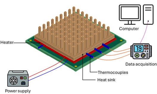
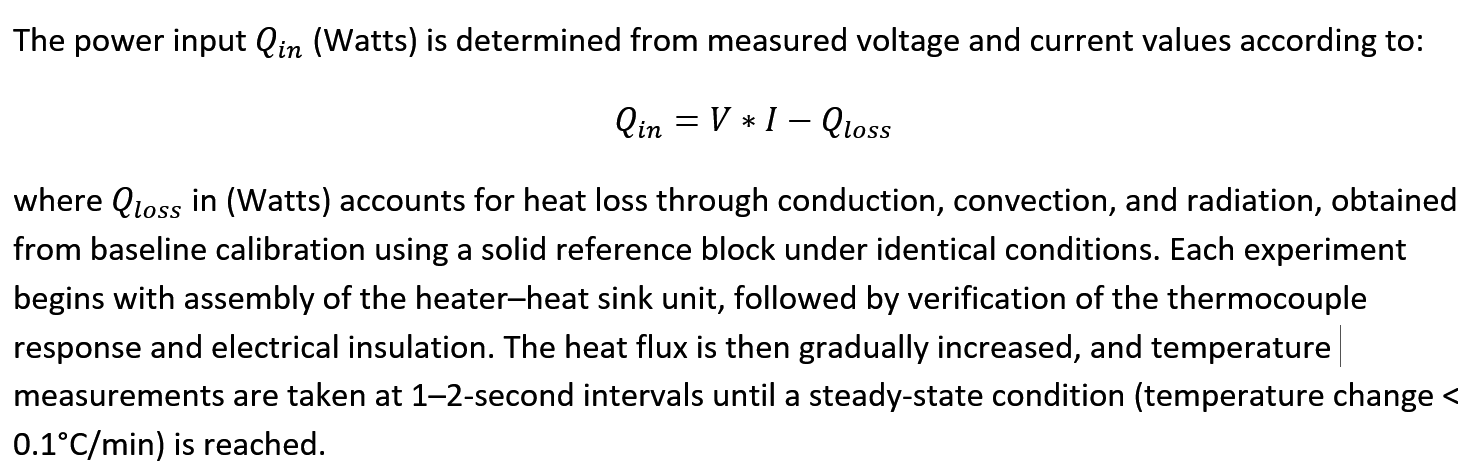
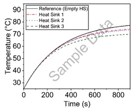
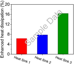
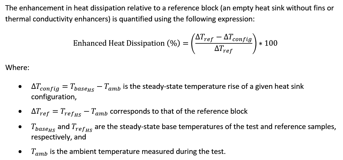



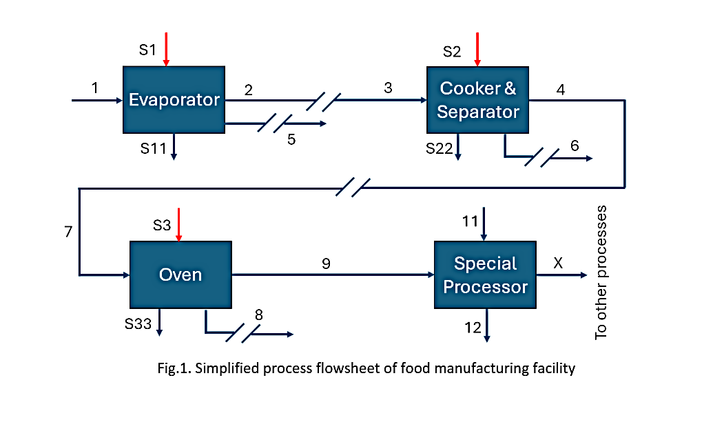
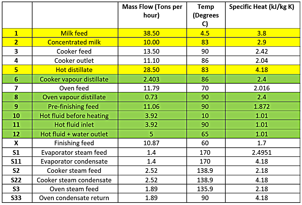
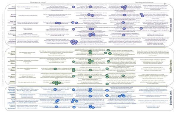
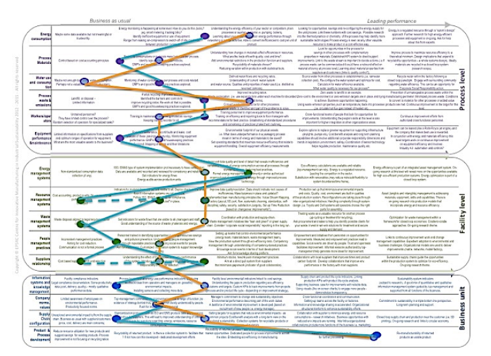
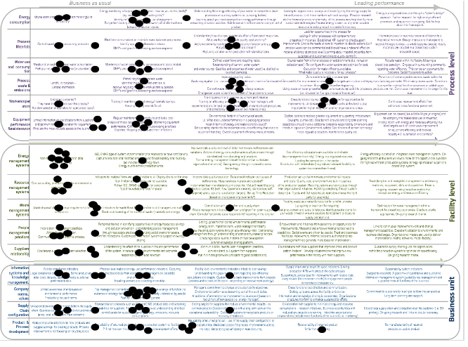
 Authors: Paola Seminara (Edinburgh Napier University); Alasdair Reid (Edinburgh Napier University).