You can now view the recording of the ACE-Lab and agentic engineering workflows webinar, as part of the Complex Systems Toolkit, supported by Quanser. The webinar was live on Monday 29th June 2026, 11am-1pm BST.
This free webinar introduces practical engineering workflows, from requirements capture through to verification and validation. These concepts are demonstrated using the ACE-Lab, a low-cost, hands-on engineering learning platform, alongside MATLAB and Simulink to illustrate key stages of the workflow. The webinar also explores the emerging role of agents in engineering workflows. Through practical examples and demonstrations, it shows how agent-enabled approaches can support engineers in solving problems more effectively. During this webinar we also launched a new call providing you with an opportunity for your content to be featured in the Complex Systems Toolkit.
During this webinar we also launched a new call for contributions, providing you with an opportunity for your content to be featured in the Complex Systems Toolkit.
For more about the webinar, including the event programme and speaker bios, click here.
To enable closed captions on Vimeo, click the CC button in the video player.
Any views, thoughts, and opinions expressed herein are solely that of the author(s) and do not necessarily reflect the views, opinions, policies, or position of the Engineering Professors’ Council or the Toolkit sponsors and supporters.
Related INCOSE Competencies: Toolkit resources are designed to be applicable to any engineering discipline, but educators might find it useful to understand their alignment to competencies outlined by the International Council on Systems Engineering (INCOSE). The INCOSE Competency Framework provides a set of 37 competencies for Systems Engineering within a tailorable framework that provides guidance for practitioners and stakeholders to identify knowledge, skills, abilities and behaviours crucial to Systems Engineering effectiveness. A free spreadsheet version of the framework can be downloaded.
This resource relates to the Systems Thinking, Systems Modelling and Analysis, Integration, and Technical Leadership INCOSE competencies.
AHEP4 mapping: This resource addresses several of the themes from the UK’s Accreditation of Higher Education Programmes fourth edition (AHEP4): Analytical Tools and Techniques (critical to the ability to model and solve problems), and Integrated / Systems Approach (essential to the solution of broadly-defined problems).
Educational level: Beginner; Intermediate.
Learning and teaching notes:
Modern engineering is increasingly digital, interconnected, and system oriented. To prepare students for this evolving landscape, the Automatic Control Engineering (ACE) Model offers a systems-driven, application-focused framework for practical control engineering education. Developed through a MathWorks-funded project launched in the summer of 2025, the ACE-Model unifies three complementary components that together cultivate systems thinking and model-based systems engineering competence:
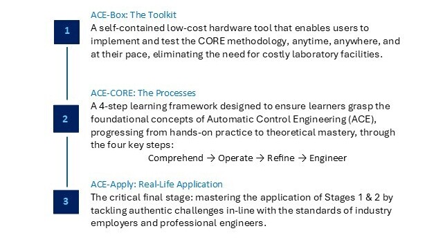
ACE-Box: The Toolkit
ACE-CORE: The Processes
ACE-Apply: Real-World Application
Learners have the opportunity to:
Engage with the entire ACE-CORE (Comprehend – Operate – Refine – Engineer) framework.
Experience a welcoming and accessible introduction to ACE, without an early overemphasis on mathematics. This stands in contrast to the traditional approach, where topics such as Laplace transforms are introduced early on, often creating unnecessary barriers to engagement (Abou-Hayt and Dahl, 2023).
Develop systems awareness and motivation.
Develop confidence, engagement, and curiosity.
Gain the technical knowledge and systems integration mindset required to thrive in the complex, adaptive landscape of digital engineering.
Teachers have the opportunity to:
Introduce control theory topics in a way that addresses the concern of students finding it difficult to link abstract control theory with the world of control engineering practice(Rossiter, 2022; Badau, et al., 2024).
Introduce industry-standard systems processes such as the V-diagram and model-based design workflows.
Progressively link theory to practice.
Support AHEP4 expectations for developing graduates who can apply integrated systems approaches to solving complex problems and the INCOSE Systems Engineering Competency areas of systems thinking, integration, and technical leadership.
What does the ACE-Model consist of?:
Figure 1:The ACE-Model: Integrating the Toolkit (ACE-Box), with the Processes (ACE-CORE), to Lead to the Real-Life Application (ACE-Apply) to build a progressive mastery in Automatic Control Engineering (ACE).
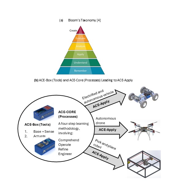
The ACE-Model is closely aligned with Bloom’s Taxonomy, see (Anderson and Krathwohl, 2001)and Figure 2(a) providing a structured pathway for students to progress through the cognitive hierarchy, while developing capabilities across multiple levels of system abstraction. Figure 2(b) offers a schematic view of the three stages of the ACE-Model, as introduced in Figure 1. An initial overview of the ACE-Model is presented here, with further details provided in the following sections.
The ACE-Box is a portable, self-contained hardware tool that brings ACE to life beyond the traditional costly, full-scale laboratories. All that is required is a laptop and the ACE-Box. Designed to support the ACE-CORE methodology, ACE-Box can be set up on a desk, in a classroom, or even at home. MATLAB and Simulink serve as the primary platforms for model-based design, enabling system modelling, control system development, and the deployment of control algorithms to physical hardware (e.g. Arduino Uno) through code generation tools.
ACE-CORE guides learners through successive levels of Bloom’s framework:
Comprehend aligns with Remember and Understand on the Bloom Taxonomy, enabling students to grasp the applications of control engineering before advancing.
Operate corresponds to Apply on the Bloom Taxonomy, as students engage directly with control systems, supported by Stage 2, making use of the ACE-Box (hardware or virtual).
Refine maps to both Analyse and Evaluate on the Bloom Taxonomy, where learners diagnose performance, compare outcomes, and adapt solutions to meet stakeholder requirements.
Engineer extends this process to system-level design and synthesis, making use of modelling and simulation tools such as MATLAB and Simulink. At this stage, students revisit the full cycle (Remember through to Evaluate), but at a higher level of integration with the use of control theory, again supported by the ACE-Box.
At each stage of CORE, learners move from recognising system components to synthesising complex interactions, mirroring the systems engineering lifecycle from requirement capture through verification and validation. This alignment supports AHEP4’s emphasis on analytical and problem-solving competence and INCOSE’s System Definition and Integration competencies.
Finally, learners progress to Create, the highest stage of Bloom’s Taxonomy, by applying their knowledge to design complete control systems for real-world applications such as drones, vehicles, and automation systems. In this way, the ACE-Model scaffolds learning in parallel with Bloom’s progression, from foundational comprehension to advanced problem-solving, design and innovation.
Together, these three pillars form a cohesive learning ecosystem: the toolkit, the process, and the application.
Figure 2:Bloom’s Taxonomy (Anderson and Krathwohl, 2001)(a) and the ACE-Model Three Stages (b).
Collaborative community:
The ACE-Model ‘sits’ within the ACE-Lab, a collaborative community of academics and industry professionals committed to developing, validating, and disseminating open-access systems education resources. The ACE-Lab approach embodies complex adaptive systems principles, where the community evolves through continuous feedback, iteration, and co-design. Membership to the ACE-Lab is open to anyone who shares our vision of advancing control engineering teaching tools and practices. Through this approach, the ACE-Model equips graduates with the knowledge and hands-on skills required to excel in modern ACE careers. Find out more about the ACE-Lab through the following website:www.ace-lab.co.uk
As an evolving community, ACE-Lab continually expands its open-access content through the active contributions of its members. New materials are regularly developed and shared, ensuring the resources remain current and relevant. Through this dynamic, collaborative approach, embodied in the ACE-Model, students not only gain technical knowledge but also develop the capacity to understand, navigate, and work effectively with complex, interconnected engineering systems.
ACE-Box: The toolkit:
The ACE-Box is based on the early development work of Control-Lab-in-a-Box(Pickering, 2023; 2025). CLB integrates sensors, actuators, and microcontroller to allow students to experience dynamic behaviour, and feedback control.
For now, two ACE-Box kits have been developed:
1. Base and sense
2. Actuate
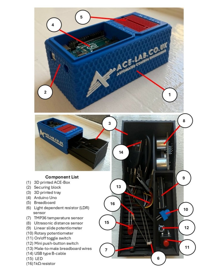
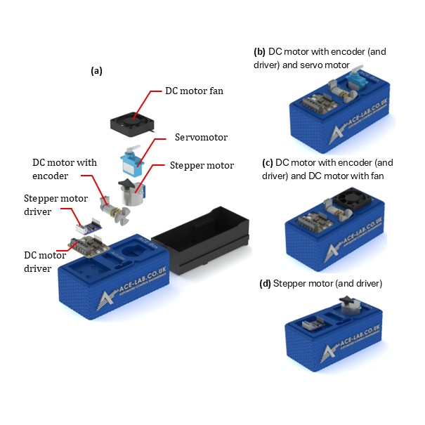
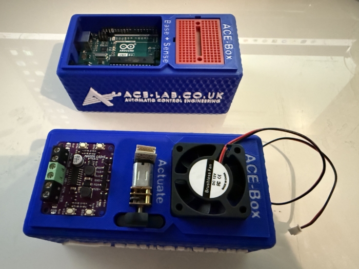
The ACE-Box (base and sense) is illustrated in Figure 3, with the 15 key components labelled, along with an exploded view of the main parts in Figure 4. The ACE-Boxesintegrate the essential microcontrollers, electronics, sensors, and actuators needed to design, implement, and test elements of digital control algorithm development, e.g. control algorithms in real time. It bridges the gap between theory and practice, allowing learners to see how abstract concepts behave in physical systems. The ACE-Box is also available as an open-access resource, with laboratory exercises included, with details provided later in this article. The ACE-Box (labelled (1) in Figure 3) and the tray (labelled (2) in Figure 3) are manufactured using 3D printing, with the necessary files available on the project website referenced above. A list of the required components and their sources is also provided on the project website, corresponding to labels (3) to (15) in Figure 3. Due to the open-source design of ACE-Lab, the library of exercises will continue to expand, supported by contributions from both academia and industry. The ACE-Box (Actuate) is illustrated in Figure 5, with the key actuator components detailed in (a), along with some typical lab set-ups (b, c and d). Figure 6 illustrates both the ACE-Box (Base + Sense) and also ACE-Box (Actuate).
Figure 3:The ACE-Box (Base and Sense).
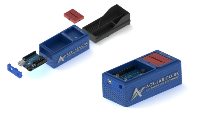
Figure 4: Assemble of the 3D Printed ACE-Box (Base and Sense).
Figure 5:The ACE-Box (Actuate).
Figure 6:ACE-Box (Actuate) Alongside the ACE-Box (Base + Sense).
ACE-CORE: The methodology:
ACE-CORE is a four-step framework designed to scaffold learning from components to system-of-systems understanding:
Comprehend: Recognise the interdependencies between components within a feedback control system.
Operate: Discover how to operate a control system from understanding system requirements to testing and validation.
Refine: Diagnose, analyse, and optimise performance using feedback principles; students apply system verification and validation approaches.
Engineer: Apply mathematics and modelling to synthesise control algorithms and architectures that achieve desired system behaviours.
The methodology explicitly develops systems thinking, and integrationcompetencies, core to both AHEP4 and INCOSE frameworks.
ACE-CORE is intentionally designed to offer a scaffolded learning experience, allowing students to build confidence step by step as they deepen their understanding. Due to its flexible structure, students can also follow a completely practical route, i.e. avoiding the modelling and simulation. The emphasis is not on rote memorisation of theory, but on progression through understanding the fundamentals of control engineering, e.g. the components that form a feedback control system.These routes enable learners to apply concepts in practical control engineering contexts and develop genuine competence.
ACE-Apply: Real-world application:
ACE-Apply is the project stage, where the skills and knowledge gained from ACE-Box and ACE-CORE are consolidated by tackling authentic challenges aligned with the expectations of industry and professional engineers, see Figure 2(b). At this stage, learners prove their mastery by addressing engineering application problems that reflect the standards of industry practice. The focus is on:
Applying the ACE-CORE methodology to practical control application challenges across domains such as robotics, automotive systems, drones, and industrial automation.
Bridging theory, simulation, and hardware with confidence and agility using industry standard tools and processes.
This stage reinforces AHEP4 Themes 3 and 5, particularly:
Applying integrated systems approaches to complex, real-world problems.
Managing system lifecycle activities including requirements capture, design, testing, and validation.
It also strengthens INCOSE competencies in System Realisation, Integration, and Technical Project Management, encouraging students to act as systems integrators capable of managing interfaces and dependencies across mechanical, electrical, and software domains.
By bridging theory, simulation, and hardware using industry-standard digital tools, ACE-Apply nurtures the ability to navigate complex adaptive systems, anticipate emergent behaviour, and work collaboratively within multidisciplinary engineering ecosystems.
ACE-Box activities:
Upon visiting the ACE-Lab website (www.ace-lab.co.uk), under the tab ‘ACE-Box’, the following tabs exist (with the links provided):
The “What is the ACE-Box?” page introduces educators and students to the ACE-Box platform, outlining its purpose, key features, and practical considerations such as sourcing components and 3D-printing enclosure parts.
The “Prior Exercises” page provides essential onboarding material designed to help users become familiar with MATLAB and Simulink. This includes links to the relevant OnRamp courses, guidance on installing the required software packages, and short tutorial videos that introduce the MATLAB and Simulink graphical user interfaces (GUIs).
The “Base + Sense” section contains a set of introductory tutorial exercises that use the ACE-Box (Base + Sense configuration). These activities help users get started with Simulink code generation for the Arduino Uno, while working with a range of basic sensors and electronic components.
Finally, the “Base + Sense + Actuate” section builds on the previous material by introducing actuation hardware. Using both the Base + Sense and Actuate modules, students and educators learn how to interface with and control devices such as DC motors, servomotors, and stepper motors. This section is designed to familiarise users with actuator integration and reinforce practical control engineering workflows.
Example use of ACE-Box (Base + Sense):
To demonstrate the use of the ACE-Box (Base + Sense), an introductory activity is provided, i.e. the on-off blinking of an LED. Prior to this activity, through ACE-CORE, students should receive a short introduction to microcontrollers covering key concepts such as digital input/output pins, analogue pins, and pulse-width modulation (PWM). Once students are familiar with these fundamentals, they progress to the initial exercise detailed here, which is aligned with defined learning outcomes.
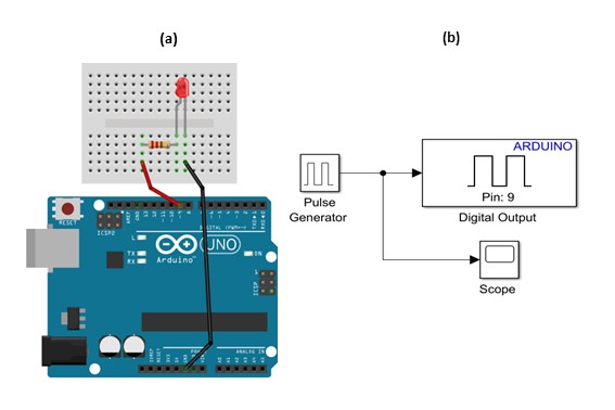
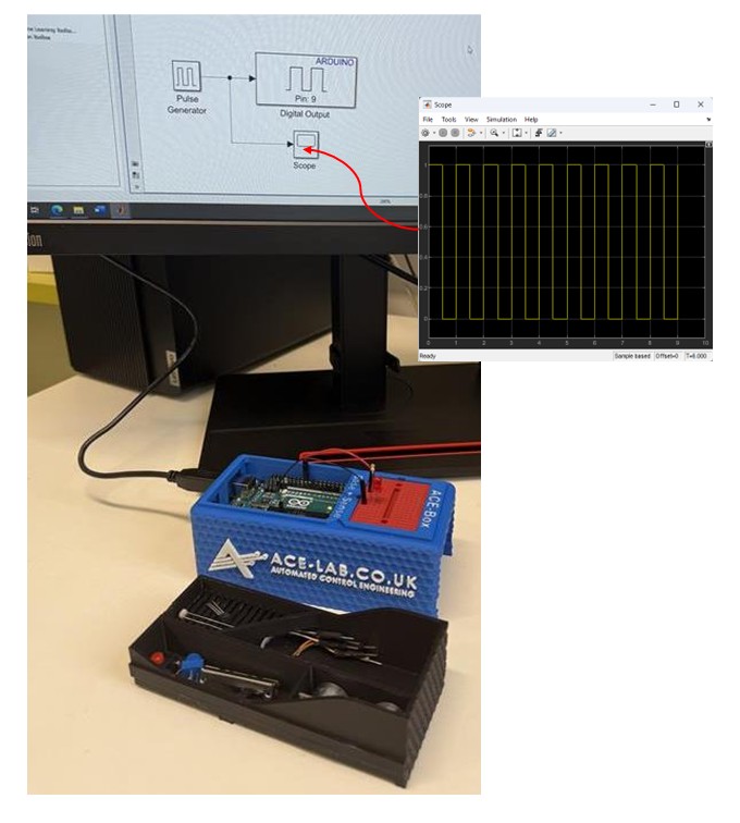
Since MATLAB and Simulink are the primary software tools used with the ACE-Box, students are first guided through installing the Simulink Support Package for Arduino Hardware. After the hardware and software setup is complete, they assemble a simple circuit, see Figure 7(a), and configure a Simulink model for the first exercise, see Figure 6(b). This initial activity requires students to control the state of a digital output pin on the Arduino, switching it on and off. The Simulink model, provided in Figure 7(b), enables students to quickly build the exercise using a visual programming approach. To run the activity, they follow a sequence of steps that includes code generation, which compiles the Simulink model into embedded C code and deploys it onto the Arduino Uno microcontroller. Once completed, the LED connected to the circuit blinks on and off according to the settings of the Simulink pulse generator. A visual of the complete set-up for this initial exercise can be found in Figure 8. At this stage, students are encouraged to experiment with the pulse generator parameters in real-time, observing how changes to the signal properties immediately affect the LED’s behaviour. Scopes can also be used (see Figure 7(b)) to visualise the pulse generator’s square-wave output, including its amplitude, period, and pulse width. This hands-on interaction reinforces the link between the initial set-up and hardware implementation while deepening their understanding of microcontrollers.
Figure 7:LED Simple Circuit (a) and Simulink for Code Generation for the on-off Blinking of an LED.
Figure 8:LED Simple Circuit Set-Up using Simulink for Code Generation for on-off Blinking of an LED.
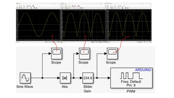
The initial exercise is designed to familiarise students with the ACE-Box and the use of Simulink’s code generation tools. This type of activity is typical for introducing students to a new software and hardware environment. The next exercise involves using pulse width modulation (PWM) to vary the brightness of the LED. This exercise involves using additional blocks in Simulink, see Figure 8, where multiple scopes are used to visualise the signals in real-time. Once students understand the fundamental building blocks of Simulink, they can quickly progress to developing feedback control systems that meet a variety of application requirements. In the authors’ view, student familiarity with Simulink makes it a more accessible platform for designing advanced control algorithms, particularly when working with sub-systems.
Figure 9:LED Simple Circuit Set-Up using Simulink for Code Generation Varying Brightness of an LED using Pulse Width Modulation (PWM).
Building on this foundation, a wide range of laboratory exercises can be developed using the electronic components involved in ACE-Box (Base + Sense), as illustrated in Figure 3, with the option to expand further by incorporating additional components. Examples of extended exercises include:
Analogue sensing and calibration with a temperature sensor
LDR characterisation and linearisation using a voltage divider
Analogue sensing and calibration with a potentiometer sensor
Digital sensing using an ultrasonic sensor
Distance-reactive LED control with proportional feedback (human-in-the-loop plant)
Closed-loop brightness control using LDR feedback and LED PWM
LED–LDR plant control experiments
In addition to sensing activities, the ACE-Box (Actuate) provides four actuators: a servomotor, a DC motor with encoder, a stepper motor, and a DC motor fan. This unit can be used independently or in combination with the Base and Sense ACE-Box to enable more advanced control experiments, such as DC motor speed control or motor control based on light intensity measurements from an LDR.
The flexibility of the ACE-Box system ensures that the number of possible exercises is effectively unlimited, as new experiments can be designed by combining existing sensors and actuators or by integrating additional measurement devices. This also allows unique coursework assignments to be created.
Summary:
The ACE-Model provides a systemic and holistic framework for practical control engineering education that:
Fosters systems thinking and model-based design literacy aligned with INCOSE and AHEP4 competencies.
Connects abstract control theory to complex, real-world systems through accessible hands-on experiences.
Encourages progression from component-level comprehension to system integration.
Builds confidence and motivation through authentic engagement with digital and physical systems, preparing graduates for engineering practice in a complex, interconnected world.
Acknowledgements:
Dr James E. Pickering gratefully acknowledges the support from MathWorks, whose funding made this project possible. He also extends his sincere thanks to Hari Sudeskkumar for his exceptional engineering design contributions and 3D-printing work. The authors would like to thank the Project Advisory Group (PAG) for their valuable guidance throughout the development of this work.
References:
Abou-Hayt, I. and Dahl, B., 2023. A Critical Look at the Laplace Transform Method in Engineering Education. IEEE Transactions on Education, 67(4), pp.542-549.
Anderson, L.W. and Krathwohl, D.R., 2001. A taxonomy for learning, teaching, and assessing: A revision of Bloom’s taxonomy of educational objectives: complete edition. Addison Wesley Longman, Inc..
Badau, N.E., Popescu, T.M., Mihai, M., Dulf, E.H. and Muresan, C.I., 2024. Bridging the gap between control theory and practice: From simple controller design to a practical microcontroller implementation. IFAC-PapersOnLine, 58(26), pp.124-129.
Pickering, J.E., 2023. Control-Lab-in-a-Box: Bridging the Gap between Control Theory and Engineering Practice. In UK and Ireland Engineering Education Research Network Conference Proceedings 2023.
Pickering, J.E., 2025. Leveraging Control-Lab-in-Box (CLB) to Teach Control Engineering on Future Vehicle Technologies MSc. IFAC-PapersOnLine, 59(7), pp.31-35.
Rossiter, J.A., 2022. Future trends for a first course in control engineering. Frontiers in Control Engineering, 3, p.956665.
Any views, thoughts, and opinions expressed herein are solely that of the author(s) and do not necessarily reflect the views, opinions, policies, or position of the Engineering Professors’ Council or the Toolkit sponsors and supporters.
Downloads: A PDF of this resource will be available soon.
Who is this article for?: Thisarticle should be read by educators at all levels in higher education who are seekingto provide students with an overall perspective on complex systems in engineering.
Related INCOSE Competencies: Toolkit resources are designed to be applicable to any engineering discipline, but educators might find it useful to understand their alignment to competencies outlined by the International Council on Systems Engineering (INCOSE). The INCOSE Competency Framework provides a set of 37 competencies for Systems Engineering within a tailorable framework that provides guidance for practitioners and stakeholders to identify knowledge, skills, abilities and behaviours crucial to Systems Engineering effectiveness. A free spreadsheet version of the framework can be downloaded.
This resource relates to the Systems Thinking and Critical Thinking INCOSE competencies.
AHEP mapping: This resource addresses several of the themes from the UK’s Accreditation of Higher Education Programmes fourth edition (AHEP4): Analytical Tools and Techniques (critical to the ability to model and solve problems), and Integrated / Systems Approach (essential to the solution of broadly-defined problems).
Engineering systems today are increasingly complex, interconnected, and adaptive. To understand and manage them effectively, engineers must move beyond reductionist thinking where systems are broken into isolated parts and adopt systems thinking, which views systems as wholes made up of interacting components.
At the heart of this perspective lies emergence, a defining characteristic of complex systems. Emergence refers to properties or behaviours that arise from interactions among components but cannot be predicted or understood by examining those components in isolation. Appreciating emergence helps engineers anticipate how individual design decisions can produce system-level outcomes, sometimes beneficial, sometimes negative and unintended.
This article introduces the concept of emergence as one key characteristic of complex systems, situates it within systems thinking, and provides practical guidance for recognising and managing emergent behaviours in engineering practice.
1. What is a system?:
A system can be defined as “a set of interconnected elements organised to achieve a purpose” (Meadows, 2008). Systems possess structure (components), relationships (interactions), and purpose (function). Engineering systems such as aircraft, power grids, transport networks, or data infrastructures are composed of numerous subsystems that depend on each other.
Crucially, systems thinking emphasises interdependence and feedback. The behaviour of the whole cannot be fully explained by the behaviour of the parts alone. Properties such as resilience, adaptability, and emergence result from interactions within the system’s structure and environment. Recognising these relationships is essential to understanding how system-level behaviours arise.
Emergence describes the appearance of new patterns, properties, or behaviours at the system level that are not present in individual components. These properties are often irreducible: they cannot be explained solely by analysing each part separately (Holland, 2014).
Researchers distinguish between:
Weak emergence – behaviours that are theoretically predictable if all component interactions were known but are practically impossible to compute due to complexity (e.g. traffic flow patterns).
Strong emergence – properties that are fundamentally novel and irreducible to component-level descriptions (e.g., consciousness in biological systems).
In engineering, most emergent behaviours are weakly emergent: complex yet explainable with sufficient data and computational tools such as agent-based modelling or system dynamics.
A key caveat is that emergence depends on perspective and system boundaries. What seems emergent at one scale (e.g., the stability of a power grid) might appear straightforward when viewed at another. Therefore, engineers must define boundaries and assumptions clearly when analysing emergence.
3. Why emergence matters in engineering:
Emergence shapes how engineering systems behave, evolve, and sometimes fail. It can produce both desired outcomes (like adaptability or resilience) and undesired ones (like instability or cascading failure).
Understanding emergence enables engineers to:
anticipate how local interactions scale up to global system behaviour;
design feedback loops and architectures that promote stability; and
identify potential points for intervention when emergent behaviour becomes undesirable.
For instance, in cyber-physical systems, emergent coordination can enhance efficiency, but it may also create unpredictable vulnerabilities if feedback loops reinforce errors. Engineers therefore must not only observe emergence but learn how to influence it through design and governance.
4. Recognising and managing emergent behaviour:
Recognising emergence
Engineers can identify emergence by looking for:
System-level patterns that do not trace directly to any single component (e.g. global traffic flow or collective oscillations in a power grid).
Unexpected behaviours, such as new failure modes or self-organising phenomena.
Scale-dependent properties, where behaviour changes qualitatively as the system grows or interacts with its environment.
Adaptive or learning responses, where the system adjusts without explicit central control.
Intervening in emergent systems
Not all emergence is beneficial. Engineers often need to mitigate unwanted emergent behaviours such as instability or inefficiency while reinforcing desirable ones. Effective approaches include:
Redesigning interactions rather than individual components, focusing on how feedback and connectivity shape outcomes.
Introducing constraints or buffers to dampen runaway feedback loops.
Enhancing diversity and modularity so subsystems can adapt locally without propagating failures globally.
Monitoring system states continuously, using sensors, data analytics, or digital twins to detect emergent behaviour early.
Managing emergence requires humility: complex systems cannot be fully controlled, only influenced. The goal is to guide system dynamics toward safe and productive outcomes.
5. Illustrative examples of emergence in engineering systems:
Network systems
The Internet exemplifies emergence: billions of devices follow simple communication protocols, yet collectively create a resilient, adaptive global network. No single node dictates its performance; instead, routing efficiency and viral content propagation arise from local interactions among routers and users.
Transportation systems
Urban traffic patterns such as congestion waves, spontaneous lane formation, and adaptive rerouting emerge from individual driver behaviour and infrastructural design. Traffic engineers use simulation models to study how simple decision rules generate complex city-wide flows.
Energy systems
Electrical grids maintain frequency and voltage stability through distributed interactions among generators, loads, and controllers. Emergent synchronisation enables reliability, but loss of coordination can cause cascading blackouts showing both beneficial and harmful emergence.
Manufacturing systems
In smart factories, machines and sensors collaborate autonomously, producing system-wide optimisation in scheduling and quality control. Adaptive algorithms and feedback loops create emergent flexibility beyond what central planning alone could achieve.
6. Practical guidance for engineers and educators:
For engineers, the key is to design with emergence in mind:
focus on local rules that encourage desirable global behaviour;
incorporate feedback and sensing to detect changes early; and
use modular, diverse architectures to enhance resilience.
For educators, teaching emergence provides an opportunity to bridge theory and practice. Software such as NetLogo and Insight Maker allows students to visualise emergent behaviour through agent-based and system-dynamics models. Linking engineering examples to ecological, social, or digital systems helps learners appreciate the universality of emergence.
Conclusion:
Emergence is not an anomaly to be avoided but a natural attribute of complex systems. It challenges traditional engineering by revealing that system behaviour often arises from relationships, not components.
Understanding emergence equips engineers to recognise interdependencies, design adaptive solutions, and work with complexity rather than against it. By embracing systems thinking, engineers can create technologies that are not only functional but resilient, sustainable, and aligned with real-world dynamics.
References:
Holland, J.H. (2014). Complexity: A Very Short Introduction. Oxford: Oxford University Press.
Johnson, S. (2001). Emergence: The Connected Lives of Ants, Brains, Cities, and Software. New York: Scribner.
Mitchell, M. (2009). Complexity: A Guided Tour. Oxford: Oxford University Press.
Bar-Yam, Y. (2003). Dynamics of Complex Systems. Cambridge, MA: Perseus Publishing.
Helbing, D. (2013). Globally networked risks and how to respond. Nature, 497(7447), 51-59.
Any views, thoughts, and opinions expressed herein are solely that of the author(s) and do not necessarily reflect the views, opinions, policies, or position of the Engineering Professors’ Council or the Toolkit sponsors and supporters.
Authors: Dr Matteo Ceriotti (University of Glasgow), Niven Payne (Fujitsu UK), Giulia Viavattene (University of Glasgow), Ellen Devereux (Fujitsu UK), Dr David Snelling (Fujitsu UK) and Matthew Nuckley (Fujitsu UK)
Abstract: A partnership between the University of Glasgow, Fujitsu UK, Astroscale and Amazon Web Services was established in response to a UK Space Agency call on Active Debris Removal mission design. This is the process of de-orbiting space debris objects from low Earth orbit with a dedicated spacecraft. The consortium brought together different but complementary expertise and tools to develop an algorithm (using machine learning and quantum-based computing) to design multiple-debris removal missions, able to select feasible sequences of debris objects among millions of permutations, in a fraction of the time of previous methods, and of better performance in terms of time and propellant required.
Overview
Space and its services have become part of everyone’s daily life, quietly. Things like mapping, geolocation, telecommunication services and weather forecast all depend on space assets. The continuous and increasing exploration and exploitation of space heavily depends on sustainability: defunct satellites and other spacecraft and launcher parts that became part of space debris population, or “junk”, increasing the threat of collision for current and future missions. There are 34,000 objects larger than 10 cm, and 130 million smaller than 1 cm, including non-operational satellites, upper stage rocket bodies, satellite parts, etc. Most of these objects are in the low Earth orbit region (below 1000 km), which is where most satellites operate.
Design of new satellites for demise prevents the creation of further debris. Active debris removal (ADR) aims dispose of debris objects that are currently in orbit. ADR actions require a “chaser” spacecraft to grapple a “non-cooperative” target, and transfer it to an orbit low enough that it will eventually de-orbit and burn in the atmosphere in a relatively short amount of time.
The idea
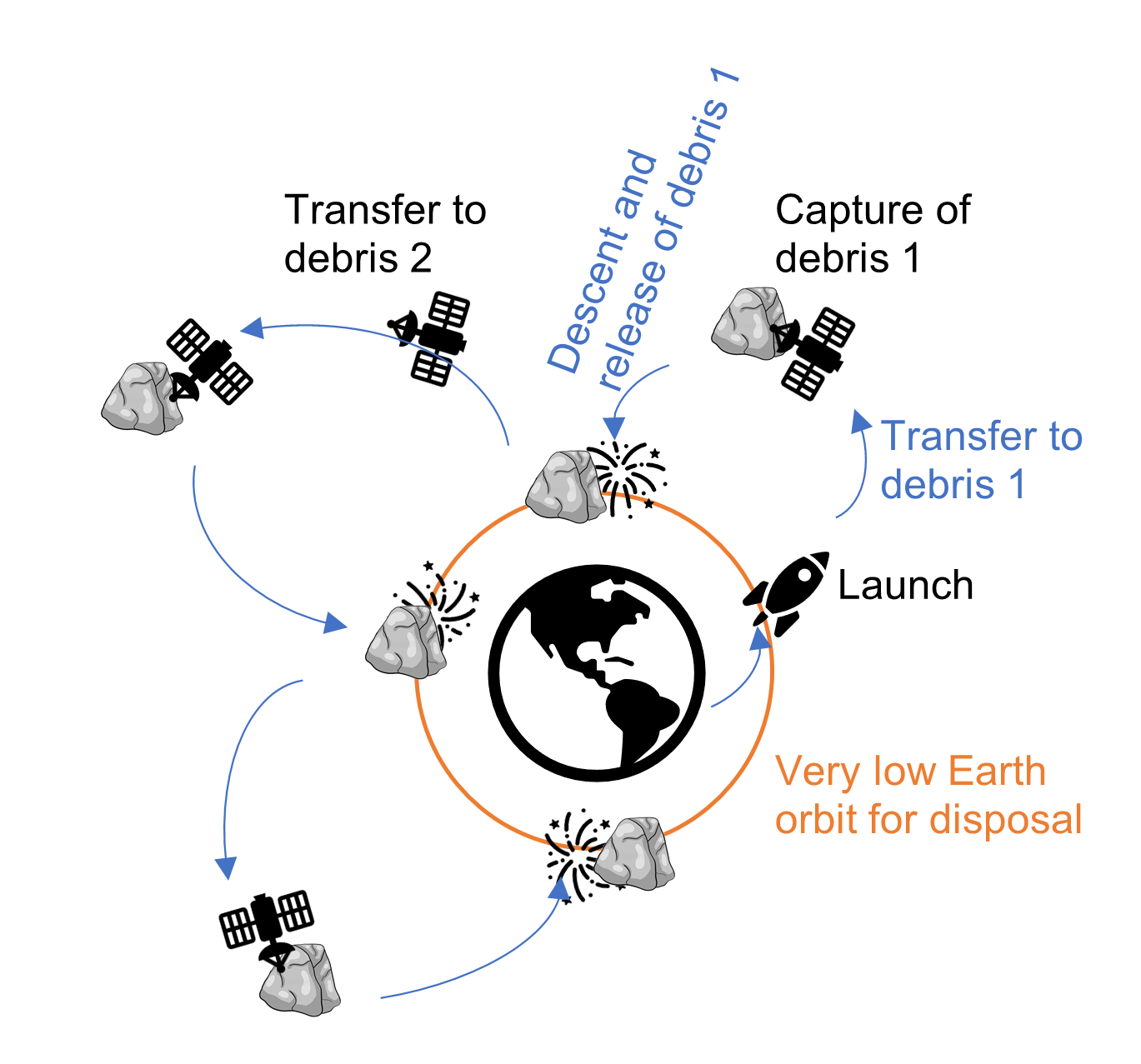
Many ADR missions would be required to make a substantial contribution in diminishing the debris population. The business challenge was to investigate how we could make space debris removal missions more commercially viable. This project investigated the feasibility, viability and design of removal and disposal of multiple debris objects using a single chaser spacecraft. The mission scenario involves a spacecraft that transfers to the orbit of one or more objects, captures it (or them), and then transfers to a lower orbit for release and disposal. At low altitude, the atmospheric drag will quickly cause the object to rapidly fall and burn in the atmosphere. In the meantime, the chaser spacecraft will transfer to another object (or set of objects) and continue the mission.
The problem
With million pieces of space junk, there are multiple trillions of permutations for ADR missions between these objects, that would need to be investigated, to efficiently remove even only a few of them. Since orbital transfers have no analytical closed-form solutions, an optimisation strategy must be used to find a solution to trajectory design problems, which is generally computationally demanding.
Our solution
The aim of this project was to make space debris removal missions more commercially viable, through a new solution that allows fast mission planning. First, an Artificial Neural Network (ANN) is trained to predict the cost of orbital transfer to and disposal of a range of debris objects quickly. Then, this information is used to plan a mission of four captures from candidate possible debris targets using Fujitsu’s quantum-inspired optimisation technology, called Digital Annealer (DA), by formulating the problem as a quadratic unconstrained binary optimisation. We used Astroscale’s mission planning data and expertise, and run the algorithms on the Amazon Web Services (AWS) Sagemaker platform. For technical details on our approach, the reader is referred to the publications below.
Outcomes
In a test-scenario, we showed that our solution produced a 25% faster mission, using 18% less propellant when compared to an expert’s attempt to plan the mission using the same assumptions; this was found 170,000 times faster than current methods based on an expert’s work.
Partnership
The project involved the partnership of four institutions, with areas of contributions described in the following diagram:
We believe the key to the success of the partnership was the different, but complementary areas of expertise, tools offered, and contribution of each partner into the project. It may be easier to rely on existing network of contacts, often with similar areas of expertise. However, this project shows that the additional effort of creating a new partnership can have great benefits, that overcome the initial difficulties.
Project set up
An initial contact between Fujitsu and UofG defined the original idea of the project, combining the existing expertise on discrete optimisation (Fujitsu) and multi-body space missions (UofG). The team was strengthened by expertise in active space debris removal (Astroscale) and cloud computing (AWS). The project proposal was funded by the United Kingdom Space Agency (UKSA), for a duration of four months, from September 2020 to January 2021.
Due to the on-going global pandemic, the project was run entirely online, with weekly meetings on Microsoft Teams. Fujitsu, as team lead, was responsible for planning and scheduling of tasks, as well as integration of code and reporting.
Lessons learned and reflections
Reactivity in preparing a project proposal was fundamental for the project: The very first contact between the partners was made at the end of July 2020, the proposal was submitted in mid-August and the project officially kicked-off in September.
Given the short timeframe, it was important to conceive a project proposal that fit the scope of the funder, but also matches with available expertise and personnel. It was also critical to frame the business challenge in the proposal.
From the point of view of the academic team, and again given the short window between notification of successful application and start of the project, these factors were crucial for the success of the project:
Immediate availability of an internal candidate as nominated Research Assistant – there would have been no time to open a new position and recruit externally.
An excellent researcher was particularly important, as there was no time to account for potential errors in the methods and their implementation.
A candidate with experience aligned with the project was sought – there would have been no time to train new staff.
A PhD student in the research group was the best candidate for the project: at the cost of taking a leave-of-absence from the PhD studentship, the project constituted a unique experience with industrial collaboration, enriched their CV through a ground-breaking project, added a conference and a journal paper to their track record, and eventually opened new areas of investigation for the rest of the PhD studentship.
It would have been probably unthinkable – or at not very credible – to deliver a project with new partners remotely without any in-person meeting before the pandemic; however, this turned out to be an enabler for this project, allowing to maximise time on actual development and save on travel costs.
Further information
G. Viavattene, E. Devereux, D. Snelling, N. Payne, S. Wokes, M. Ceriotti, Design of multiple space debris removal missions using machine learning, Acta Astronautica, 193 (2022) 277-286. DOI: 10.1016/j.actaastro.2021.12.051
D. Snelling, E. Devereux, N. Payne, M. Nuckley, G. Viavattene, M. Ceriotti, S. Wokes, G. Di Mauro, H. Brettle, Innovation in planning space debris removal missions using artificial intelligence and quantum-inspired computing, 8th European Conference on Space Debris, ESA/ESOC, Darmstadt, Germany (Virtual Conference), 2021.
Any views, thoughts, and opinions expressed herein are solely that of the author(s) and do not necessarily reflect the views, opinions, policies, or position of the Engineering Professors’ Council or the Toolkit sponsors and supporters.
 You can now view the recording of the ACE-Lab and agentic engineering workflows webinar, as part of the Complex Systems Toolkit, supported by Quanser. The webinar was live on Monday 29th June 2026, 11am-1pm BST.